OI_EC2-XC645CX_A1_A2L_A3_EN_Rev01_866933.docx EC2-XC645CX 8/54
WIRING & ELECTRICAL CONNECTIONS
5.1 General warnings
Before connecting cables make sure the power supply complies with the instrument’s
requirements.
Separate the probe cables from the power supply cables, from the outputs and the power
connections.
Do not exceed the maximum current allowed on each relay 3A resistive, see also Technical
Features, in case of heavier loads use a suitable external relay.
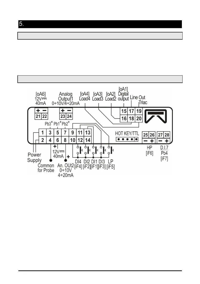
5.2 Wiring connections
• Always use a class 2 transformer with minimum power 5 VA such as TF5.
• Terminals [21-22], [23-24], [25-26], [27-28] are provided with JST 2 PINS connectors, they
require the CABCJ15 (1.5 m) or CABCJ30 (3 m) wiring cables.