1)
Based on: DIN VDE 0298-4 (conductor temperature 90 °C, laying method E)
Table 9: Connection to the input power grid
The grid must provide a R
SCE
≥ 250 Ω, together with a system input current greater than 16 A on
each phase to be in line with standard EN 61000-3-12.
For users who are unable to qualify for EN 61800-3 Category C2, an external EMI filter can be fitted
in front of the drive.
3.4.5 Compressor connection
Table 10 shows information on how to connect the drive to the compressor. The connecting cables
are rated at 90 °C. The cable cross-section is rated for a maximum ambient temperature of 60 °C.
1)
Based on: DIN VDE 0298-4 (conductor temperature 90 °C, laying method E)
Table 10: Compressor connection
The drive output terminals are named U, V, W. In addition to this, there is a PE terminal which must
be wired directly to the compressor earth point. The cables should be as short and the ferrites as
close to the drive as possible. In any case the motor cables should not cross any other cables to
avoid EMI issues. By using a shielded cable, which is in general not designed for cable lengths less
than 2 metres, ensure proper shielding on both sides to get best results. One ferrite is needed for
the output cable (U,V,W). The use of isolated ring and isolated blade terminals is mandatory for all
terminals to maintain the IP20 class.
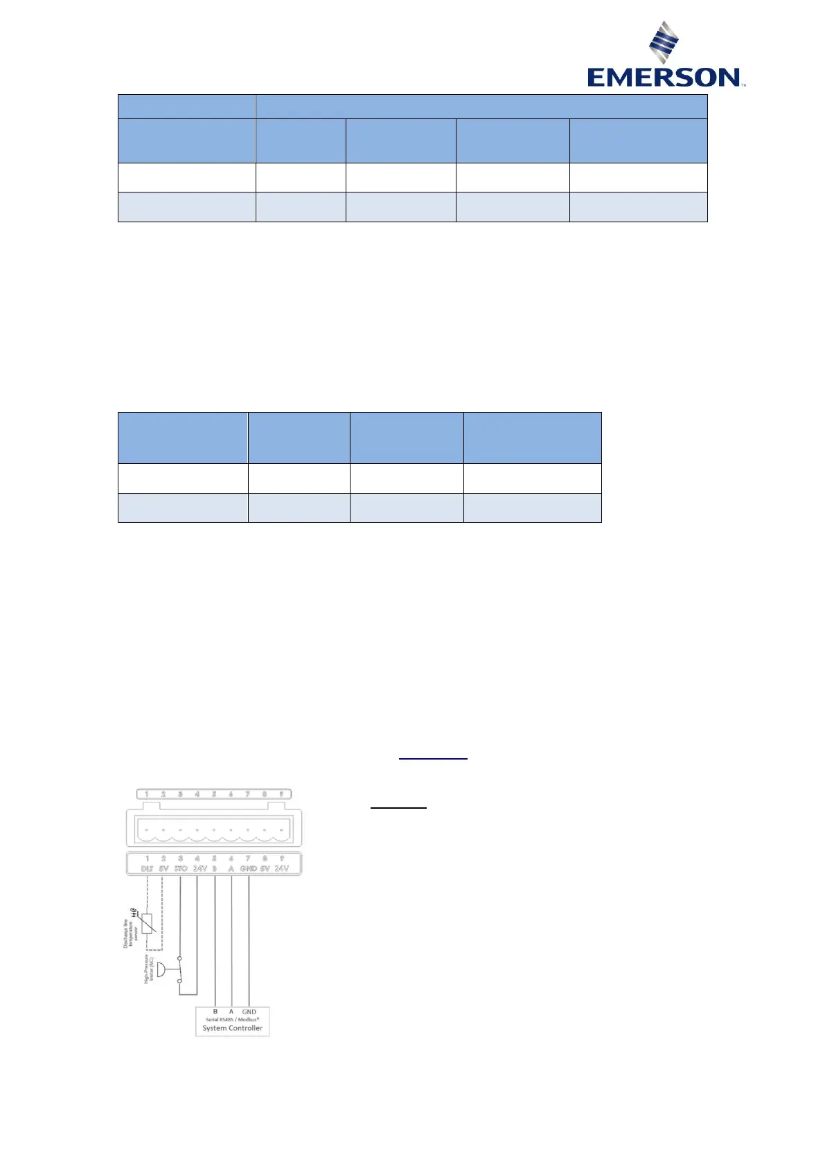
3.4.6 Control terminal
Each drive has a 9-pin control terminal including the 9-pin plug counterpart (JITE PTB750B-00-1-09-
3). The 5 V terminals are designed to provide voltage supply to the DLT input, the STO input, ie,
high-pressure limiter (see paragraph 3.4.8 "STO input"), and if necessary to the RS485 serial
communication circuit. No other usage of these 5 V and 24 V power supplies is allowed.
Figure 5: Control terminal