AGL_Sol_EV3_E_Rev_02 21
Reasons for moving to Speed-Drop Protection mode:
▪ Overtemperature of the power module
▪ Overtemperature in the discharge line
▪ Operating in field weakening range
▪ Output overcurrent
▪ Input overcurrent
▪ Drive ambient temperature foldback
The controller can avoid moving to the Speed-Drop Protection mode by using registers [37], [39],
[40], [41], [42] and [46] for control purposes.
6.2 Power module speed-drop protection
Considering the described speed-drop protection behaviour, the logic for the power module
protection follows the diagram below:
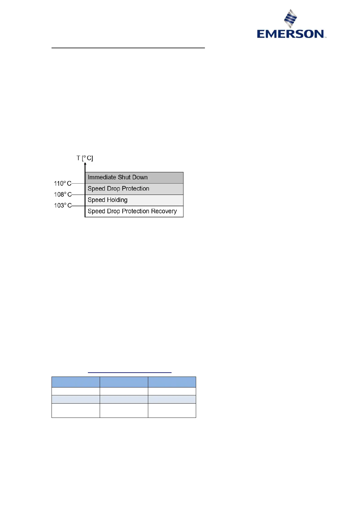
Figure 13: Power module speed drop protection logic
If the temperature reaches 108 °C, the drive will take over the speed demand and will reduce it to
the speed-drop protection speed, in an attempt to reduce the module temperature.
If the speed reaches its speed-drop protection value, and the temperature is still above 108 °C for
30 seconds, the drive will automatically shut down the compressor.
However, if the temperature decreases below 108 °C, the drive will enter in the Speed Holding area,
where the speed is kept constant, until the temperature goes below the recovery value, ie, below
103 °C.
If the temperature goes below the recovery value, the drive will return to the speed commanded
initially.
6.3 Discharge line temperature protection
If a discharge line temperature sensor is wired and activated via register [207] the drive will control
this temperature. This is achieved via the DLT value [77] considering a lower speed-drop protection
limit readable via register [46] or configurable via register [110] and an upper maximum limit [27]. For
YPV* compressors the DLT trip limit ([27]) is configurable through register [222]. The register can be
set within the range of 135 to 150 °C. The configured value will be written in register [27].
Once the drive goes into speed-drop protection mode the functionality is the same as described in
Chapter 6.1 "Speed-Drop Protection mode".