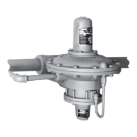
Type 92S
11
Startup with Existing Regulator
Installation After Normal Shutdown
1. Open the upstream and downstream block valves
and let the regulator take over control at the
existing pilot control spring setting.
2. If a bypass line is used, slowly control the bypass
line block valve.
Shutdown
1. If a bypass line is used, slowly open the
bypass line block valve while monitoring the
downstream pressure.
2. Close the control line shutoff valve.
3. Close the downstream block valve.
4. Close the upstream block valve.
5. If a pressure-loaded or on-off pilot is used, close
the needle valve to the pilot.
6. Vent the regulator and control line to release any
trapped pressure.
Maintenance
Regulator parts are subject to normal wear and must
be inspected periodically and replaced as necessary.
The frequency of inspection and replacement depends
upon the severity of service conditions and upon
applicable codes and government regulations.
!
WARNING
To avoid personal injury resulting from
sudden release of pressure, isolate the
regulator from all pressure and cautiously
release trapped pressure from the
regulator before attempting disassembly.
Types 6492L, 6492H, 6492HT, 6492HM,
and 6492HTM Pilots
These procedures are to be performed if inspecting,
cleaning, or replacing any pilot parts, or if cycling,
erratic control, or too high or too low an outlet (control)
pressure is noted. Perform only those procedures
in this section required to correct the problem. Key
numbers refer to Figure 4 unless otherwise noted.
Note
Before performing any maintenance,
loosen the hex nut (key 16), if used,
and turn the adjusting screw (key 15) or
handwheel (key 38) counterclockwise
until all compression is removed from
the control spring (key 12). Remove
the pilot from the pipe nipple and
connectors (keys 82 and 83, Figure 6).
1. Unscrew the plug guide (key 2). Remove the
screen (key 77), plug (key 4), plug spring (key 3),
and stem (key 7). Unscrew the seat ring (key 5).
Examine the seat ring and plug seating surfaces
for damage.
2. Clean and replace parts as necessary. Apply
sealant to the seat ring threads. Thread the seat
ring into place and tighten it to between 19 and
25 foot•pounds (26 and 34 N•m) of torque.
3. Handle the parts carefully, and place the plug
spring (key 3) in the plug guide (key 2). Slide the
plug (key 4) over the spring and into the plug
guide. Place the screen (key 77) onto the plug
guide. Place the stem (key 7) in the center hole
of the plug guide. Apply sealant to the plug guide
threads, and screw the guide plus attached parts
into the body (key 1).
4. Remove the pipe plug (key 74). Then remove
the bleed restriction (key 76) on Types 6492L,
6492H, and 6492HT or the pipe plug (key 94) on
Types 6492HM and 6492HTM. Clean and replace
the bleed restriction or pipe plug as necessary.
5. Apply sealant to the threads of the bleed restriction
(key 76) or pipe plug (key 94) and install.
6. Apply sealant to the threads of the pipe plug
(key 74). Thread the pipe plug into place and
tighten using 5 to 15 foot•pounds (7 to 20 N•m)
of torque.
7. Remove the cap screws (key 17), spring case
(key 14), control spring (key 12), and upper spring
seat (key 13) from the body.
8. Remove the lower spring seat (key 11, Types 6492H
and 6492HT pilots only) or diaphragm plate
assembly (key 24, Type 6492L pilot only),
diaphragms (key 10), and diaphragm gasket
(key 18) from the body. Inspect and clean the
diaphragm gasket, and replace if necessary.

 Loading...