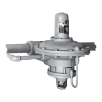
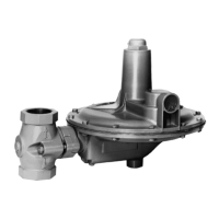
Type 92S
9
In the event that the upstream valve fails, the
downstream regulator will prevent downstream
pressure from rising above safe operating levels.
It is recommended to install some type of warning
system, such as a sentinal relief valve, to warn the
operator that a valve has failed in the system. This
will prevent prolonged operation with one valve, which
could cause valve trim wear and noise associated with
operation at high differential pressures.
When operating in most steam systems, valve
setpoints should be in strict accordance to ASME
Boiler and Pressure Vessel Code, section VIII. The
Type 6492HM (or 6492HTM) safety override pilot
should be set at 10 psig (0,69 bar) or 10% above
maximum downstream operating pressure of the
second valve, whichever pressure is greater. For
example, most HVAC systems operate at 15 psig
(1,03 bar), so the safety override pilot should be set no
higher than 25 psig (1,7 bar).
Installation
!
WARNING
Personal injury, equipment damage,
or leakage due to escaping steam
or bursting of pressure-containing
parts may result if this regulator is
overpressured or is installed where
service conditions could exceed the
limits given in the Specication section
and on the appropriate nameplates, or
where conditions exceed any ratings of
the adjacent piping or piping connections.
To avoid such injury or damage, provide
pressure-relieving or pressure-limiting
devices to prevent service conditions
from exceeding those limits.
Additionally, physical damage to the
regulator could result in personal injury
and property damage due to escaping
steam. To avoid such injury and damage,
install the regulator in a safe location.
1. Only personnel qualied through training and
experience should install, operate, and maintain
a Type 92S regulator. Before installation, make
sure that there is no damage to, or debris in, the
regulator Also make sure that all tubing and piping
are clean and unobstructed.
2. A Type 92S regulator may be installed in any
orientation, as long as ow through the regulator
matches the direction of the arrow on the main valve
body. However, the regulator should not be installed
in a tall, vertical pipeline where condensate could
collect and create a pressure head affecting
regulator performance.
3. Apply steam-compatible pipe compound to the male
pipeline threads for a threaded body, or use suitable
line gaskets for a anged body. Use acceptable
piping procedures when installing the regulator.
4. If continuous operation of the system is required
during inspection and maintenance, install a
three-valve bypass around the regulator. If the
owing medium contains solids, install a properly
sized strainer upstream of the regulator.
Note
A clogged vent on the spring case of
a standard Type 6492H or 6492L pilot
may cause the regulator to function
improperly. Install and maintain a
regulator with a standard pilot so that
the spring case vent stays clear.
5. As shown in Figure 2, connect a control line as
large as possible but no smaller than 3/8-inch
(9,5 mm) diameter bushed down to the 1/4-inch
threaded NPT connection in the cylinder spacer
(1, 1-1/2, or 2-inch body size) (DN 25, 40, or 50) or
the pilot body (2-1/2, 3, 4, or 6 x 4-inch body size)
(DN 65, 80, 100, or 150 x100).
6. Locate the control line connection at least 10 pipe
diameters away from the regulator or swage and in a
section of straight pipe.
7. Do not locate the control line connection in a gate,
plug, or check valve, in an elbow, swage, or other
area of the pipeline where turbulence or abnormal
velocities may occur, or in a large-volume vessel
that can cause noticeable control lag.
8. Slope the control line away from the pilot to let
condensate drain into the pipeline.
9. Install a shutoff valve (not a needle valve) in the
control line to isolate the pilot during maintenance.
10. Install a pressure gauge in the control line, or near
the regulator, to aid in setting the outlet pressure.
11. With a pressure-loaded or on-off pilot, connect the
pressure-loading or on-off piping or tubing to the
1/4-inch threaded NPT connection in the tapped
pilot spring case.

 Loading...


