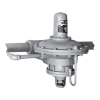
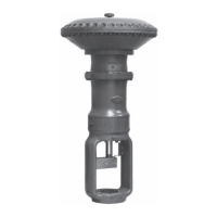
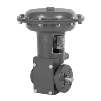
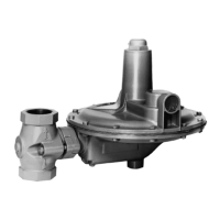
Type 92S
13
only), and the plug spacer (key 33, 2-inch
(DN 50) size only) where appropriate in
the following step.
4. Secure the hex head at the lower stem (key 9) in
a vise. Install the valve plug (key 6), seat ring
(key 7) and cage (key 5).
For 1, 1-1/2, and 2-inch sizes (DN 25, 40, and 50),
install the bafe (key 13) and the retaining ring
(key 14). Then, install the piston spacer (key 11)
down through the bafe until it makes contact with
the valve plug.
For 2-1/2, 3, and 4-inch sizes (DN 65, 80, and
100), install the plug spacer (key 33), bafe
(key 13), O-ring, washer, spring seat and piston
spacer (keys 38, 34, 32, and 11). Then, install
the cylinder (key 17), spring (key 12) and secure
with piston (key 24), piston ring (key 25), with its
open end pointing out, piston ring retainer (key 26)
and stem nut (key 15).
For the 1, 1-1/2, and 2-inch sizes (DN 25, 40, and
50), lock the stem nut (key 15) in place with a cotter
pin (key 16), but do not fold the pin ends up on top
of the stem since this can interfere with loading
pressure registration through the top stem passage.
5. Install the main piston cage assembly with
attached parts into the body. Coat the edge of
the main cylinder (key 17) with sealant and install
a new cylinder gasket (key 18) onto this edge.
6. Install a new body gasket (key 19) onto the
appropriate edge of the body.
7. For 1, 1-1/2, and 2-inch sizes (DN 25, 40, and 50),
install the stem seal (key 22) onto the cylinder
spacer (key 21) in the orientation shown in
Figure 5, and secure with the stem seal retainer
(key 23). Coat the serrated edge of the spacer
with sealant, and install the spacer edge-side-
down over the bottom cylinder.
8. For 1, 1-1/2, and 2-inch sizes (DN 25, 40, and 50),
coat both serrated edges of the top cylinder
(key 17) with sealant, install new cylinder gaskets
(key 18) on these edges, and install the cylinder.
9. For 1, 1-1/2, and 2-inch sizes (DN 25, 40, and 50),
install the top piston ring (key 25) with its open end
pointing out, ring retainer (key 26), and stem
(key 20) on the top piston. Secure these parts with
the lockwasher and hex nut (keys 40 and 41).
Install the top piston plus attached parts stem-rst
through the stem seal until the top stem contacts
the bottom stem.
10. Install the body ange (key 2) on the body, and
secure with the cap screws (key 3, not shown) for
a cast iron body or with the stud nuts (key 4) for a
steel body.
11. Install the pilot and connect all tubing as shown
in Figure 6.
12. When all maintenance is complete, refer to
the Start-up section to put the regulator back into
operation and adjust the pressure setting.
Parts Ordering
When corresponding with your local Sales Ofce about
this equipment, always reference the equipment serial
number. When ordering replacement parts, reference
the complete 11-character part number of each needed
part as found in the following parts list.
Parts List
Types 6492L, 6492H, and 6492HT
Pilots (Figure 4)
Key Description Part Number
Repair Kits (included are keys 4, 5, 7, 8, 9, 10, and 18)
Type 6492L pilot R6492LX0012
Types 6492H and 6492HT pilots R6492HX0012
1 Body
Cast iron
Type 6492L pilot 32A0404X012
Type 6492H pilot 22A0403X012
Steel
Type 6492L pilot 32A0404X052
Types 6492H and 6495HT pilots 22A0403X052
Stainless steel
Type 6492L pilot 32A0404X062
Types 6492H and 6492HT pilot 22A0403X072
2 Valve Guide, Stainless steel
For Cast iron and Steel bodies 1E391835132
For Stainless steel body 1E391835072
3 Valve Spring, Stainless steel 1E392437022
4* Inner Valve, Stainless steel
For Cast Iron and Steel bodies 1F967446172
For Stainless steel body 1F9674X0012
*Recommended spare parts

 Loading...


