Instruction Manual
D103292X012
C1 Controllers and Transmitters
March 2017
42
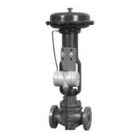
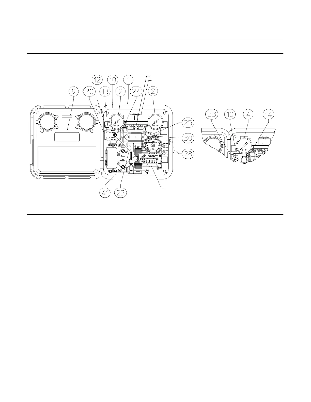
Figure 22. Typical Reverse Acting Fisher C1 Assembly
(Refer to figure 26 for the Front View of the Case & Cover Assembly)
RELAY ASSEMBLY
SUBASSEMBLY
(KEY NOS. SHOWN
IN FIGURE 24 OR 25)
NOTE:
KEYS 11, 21, AND 29 ARE NOT SHOWN
GE34729-B
GE31719-A
E1069
OPTIONAL PROCESS PRESSURE INDICATION
TRANSMITTER
SPRING-OUT CLEANING WIRE
Key Description
5* Bourdon Tube
6 Dial, aluminum
7 Screw, nylon (transmitters only)
8* Cantilever Spring, S30200
3-15 psi range
6-30 psi range
9 Nameplate, aluminum
10 Control Pressure Block
For gauge pressure instruments
w/o process pressure gauge
CF8M FMS 20B58 for standard, NACE and oxygen service
w/process gauge
SST
Key Description
11 Plug, S31600 (not shown)
used with gauge pressure only
1 req'd for standard/NACE
2 req'd for oxygen service
12 Machine Screw, steel pl (4 req'd)
13 Lockwasher, steel pl/zn pl (4 req'd)
14 Pressure Connection, S31600
Use w/process gauge
15 Pipe Plug, steel pl (not shown)
Use w/process gauge, not used w/Bourdon tube protector
*Recommended spare parts
 Loading...