Type LR125
11
!
WARNING
W7400_1
4. Remove the diaphragm (key 9).
5. Remove the top plug O-rings (keys 14 and 70).
6. Check all components for damage or wear and
replace as necessary.
7. When reassembling, be sure to lubricate all
O-rings before installing and add a thread locking
compound to the threads of the top plug.
8. Reassemble in the reverse order. Hold the top
plug (key 5). Place the parts on the top plug in the
following order:
• O-ring (key 14)
• O-ring (key 70)
• Diaphragm (key 9)
• O-ring (key 10)
• Bottom Plug (key 11)
• Flanged Hex Nut (key 13) [On 1 in. / DN 25
body, lock washer (key 130) then socket head
screw (key 129)]
9. Tighten anged hex nut (key 13) to proper torque
(see Table 9).
10. Completely reassemble the unit according to the
assembly procedures provided on page 9.
Travel Indicator Assembly Maintenance
Travel indicator assembly key numbers are referenced
in Figures 7, 10 and 14. The indicator assembly
can be removed and installed without removing the
bonnet (key 2) from the body (key 1). Travel indicator
maintenance is performed for two reasons:
a. When damaged or worn parts need replacing.
b. When travel indicator is removed and replaced with
a travel indicator plug assembly.
Avoid personal injury or damage
to property from sudden release of
pressure or uncontrolled process
uid. Before starting to disassemble,
carefully release all pressures
according to the shutdown procedure.
Use gauges to monitor inlet, loading
and outlet pressures while releasing
these pressures.
1. Remove the indicator protector (key 22, Figure 10)
and indicator cover (key 21).
2. Remove the rst hex nut (key 4) and the indicator
washer (key 20).
3. Unscrew but do not completely remove the second
hex nut (key 4) on the top of the indicator stem
(key 15).
4. Use a wrench to remove indicator tting (key 19).
5. Lift out travel indicator assembly. If replacing travel
indicator with travel indicator plug, skip to step 9.
6. Compress the main spring (key 12). Remove the
second hex nut (key 4). Parts will separate easily
when the hex nut is removed.
7. Slide the indicator stem (key 15) out of the
indicator tting (key 19). The main spring (key 12)
and upper spring seat (key 17) will disengage.
8. If necessary, use the indicator stem (key 15) to pry
the back-up rings (key 16) and O-ring (key 18) out
of the indicator tting (key 19).
9. Check the indicator tting O-ring (key 6). Lubricate
and replace if necessary.
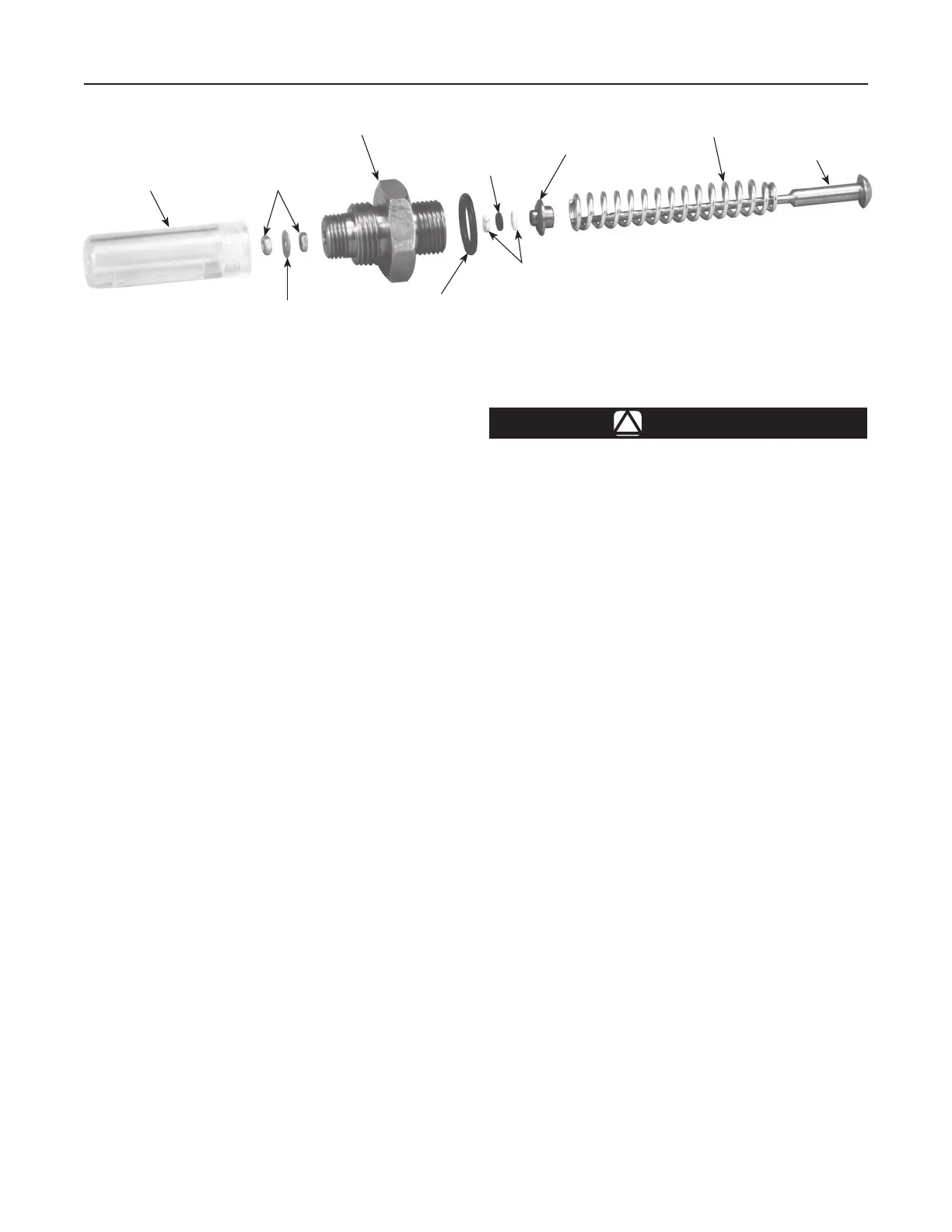
10. To replace travel indicator parts, lubricate all
O-rings, back-up rings and threads. To reassemble,
hold the indicator stem (key 15) and place the parts
on the stem in the following order (see Figure 7).
INDICATOR COVER
(KEY 21)
HEX NUTS
(KEY 4)
INDICATOR FITTING
(KEY 19)
O-RING
(KEY 18)
UPPER SPRING
SEAT (KEY 17)
MAIN SPRING
(KEY 12)
INDICATOR STEM
(KEY 15)
BACK-UP
RINGS
(KEY 16)
INDICATOR
O-RING (KEY 6)
INDICATOR
WASHER (KEY 20)
Figure 7. Travel Indicator Parts

 Loading...