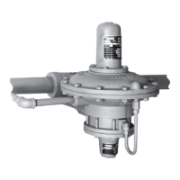
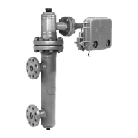
Type 667 Sizes 80 & 100
4
WARNING
To avoid personal injury due to the sud-
den, uncontrolled movement of parts,
do not loosen the cap screws when the
stem connector has spring or loading
pressure force applied to it.
Loading Connection
Key number locations are shown in figures 6 and 7,
unless otherwise directed.
1. Connect the loading pressure piping to the connec-
tion in the size 80 spring case adaptor (key 89) or in
the size 100 lower diaphragm casing (key 67).
For top-loaded actuators
1. For size 80, remove the the pipe bushing (key 78),
and connect the loading pressure piping in its place.
For size 100, remove the hex bushing (key 62) from
the upper casing (key 1), and connect the top loading
pressure piping in its place.
2. Remove the 1/4-inch bushing (key 92, figure 6; key
62, figure 7) to increase connection size, if necessary.
The connection can be made with either piping or tub-
ing.
3. Keep the length of tubing or piping as short as pos-
sible to avoid transmission lag in the control signal. If
an accessory (such as a volume booster or valve posi-
tioner) is used, be sure that the accessory is properly
connected to the actuator. Refer to the positioner in-
struction manual as necessary.
4. Cycle the actuator several times to check that the
valve stem travel is correct and that the travel occurs
when the correct pressure range is applied to the dia-
phragm.
5. If valve stem travel is incorrect, refer to the
Travel
procedure in the
Adjustments
section.
6. If the spring pressure range is incorrect, refer to the
Spring
procedure in the
Adjustments
section.
Travel
Make travel adjustments when the motion observed
during actuator travel is different from the travel
stamped on the actuator nameplate. If the
Actuator
Mounting
procedure was followed correctly, this ad-
justment should not be necessary.
When adjusting travel of a direct-acting valve, put a
slight pressure on the actuator diaphragm. This moves
the valve plug off the seat, reducing the chance of
damaging the valve plug or seat during adjustments.
1. Back the stem jam nuts (key 69, figures 6 and 7)
away from the stem connector (key 31, figures 6 and
7), and slightly loosen the stem connector cap screws.
CAUTION
Do not use wrenches or other tools di-
rectly on the valve stem. Damage to the
stem surface and subsequent damage
to the valve packing may result.
2. Tighten the locknuts together, using a wrench, then
screw the valve stem either into the stem connector to
lengthen travel or out of the stem connector to shorten
travel.
3. Cycle the actuator to check for the specified travel.
If actual travel is not equal to the specified travel, ad-
just and check travel until correct. Tighten the stem
connector cap screws when correct travel is obtained.
4. Raise the travel indicator disk by threading the
stem locknuts against the stem connector.
Spring
Make spring adjustments when the loading pressure
range applied to achieve specified travel is not equal
to the pressure range stamped on the actuator name-
plate. Refer to the Bench Set pressure range on the
nameplate when the valve contains no pressure and
the packing is loosely inserted in the bonnet. Refer to
the Maximum Allowable Supply pressure on the name-
plate when the valve is controlling the specified pres-
sure drop, and the packing is tightened to stop leaks
around the stem.
Monitor loading pressure carefully when making ad-
justments. Do not exceed the pressure specifications
of either the loading regulator or the actuator casings.
Each actuator spring has a fixed pressure span.
Changing the spring compression shifts the span up or
down to make valve travel coincide with the loading
pressure range.
Size 80 Actuator Spring
Remove cover band (key 87, figure 6), insert a rod of
approximately 1/2 inch (12.7 mm) diameter into a hole
in the spring adjustor (key 74, figure 6), and rotate the
spring adjustor with the rod. Rotating the adjustor from
left to right will increase the loading pressure required
to start actuator stem travel; opposite rotation will de-
crease the pressure required to start travel.

 Loading...