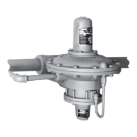
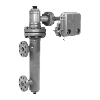
Type 667 Sizes 80 & 100
6
WARNING
Avoid personal injury from sudden re-
lease of process pressure. Before per-
forming any maintenance operations:
D Disconnect any operating lines pro-
viding air pressure, or a control signal
to the actuator. Be sure the actuator can-
not suddenly open or close the valve.
D Use bypass valves or completely
shut off the process to isolate the valve
from process pressure. Relieve process
pressure on both sides of the valve.
Drain the process media from both
sides of the valve.
D Vent the power actuator loading
pressure and relieve any actuator spring
precompression.
D Use lock-out procedures to be sure
that the above measures stay in effect
while you work on the equipment.
Size 80 Actuator Maintenance
For actuators size 80, refer to figure 4 for part names
and locations. Key number locations for Size 80 actua-
tors are shown in figure 6.
Disassembly
1. Isolate the control valve from the line pressure, re-
lease pressure from both sides of the valve body, and
drain the process media from both sides of the valve.
Shut-off all pressure lines to the power actuator, re-
lease all pressure from the actuator. Use lock-out pro-
cedures to be sure that the above measures stay in
effect while you work on the equipment.
2. Remove the tubing or piping from the connection in
the top of the spring case adaptor (key 89).
3. If the actuator has a handwheel, rotate the hand-
wheel to relieve all spring compression.
4. Remove cover band (key 87). Insert a steel rod of
approximately 1/2-inch (12.7 mm) diameter into a hole
in the spring adjustor (key 74), and rotate the spring
adjustor from right to left until spring compression is
relieved.
WARNING
To avoid personal injury due to the sud-
den, uncontrolled movement of parts,
do not loosen the cap screws on the
stem connector (key 31) when spring
force is applied.
5. If necessary, the entire actuator assembly may be
removed from the valve body by unscrewing the cap
screws from the stem connector (key 31) and remov-
ing actuator-to-bonnet bolting.
6. Unscrew diaphragm casing cap screws and nuts
(keys 13 and 14), and lift off upper diaphragm casing
(key 1).
7. Unscrew diaphragm cap screw (key 12), remove
spacer, upper diaphragm plate, diaphragm, and lower
diaphragm plate (keys 2, 4, 3, and 71). (Note: Stan-
dard and top-loaded constructions use the same key
numbers for parts. The parts look different, but they
use the same assembly and disassembly sequence.
See figure 4, Size 80 Actuator Construction for loca-
tion of parts.)
8. Unscrew cap screws (key 30), and remove lower
diaphragm casing (key 64).
9. For actuators without a snubber:
a. Unscrew the spring case adaptor cap screws
and nuts (keys 90 and 91), and remove the adaptor
(key 89) from the actuator.
b. Remove the snap ring and seal bushings (keys
72 and 7). Inspect, and if necessary, obtain a re-
placement seal bushing (key 7). Replace seal
bushing O-rings (keys 8 and 9) as required. Lubri-
cate with Lubriplate MAG-1 (key 237) lubricant or
equivalent.
c. Remove actuator spring (key 18). Unscrew cap
screws from stem connector (key 31), and remove
the stem connector. Remove stem (key 144) and
attached spring adjustor, thrust bearing, and spring
seat (keys 74, 86, and 19).
10. For actuators with a snubber (see figure 8):
a. Remove travel stop (key 84). Be certain there is
not compression in the actuator spring (key 18). If
actuator was removed from valve, secure stem
connector (key 31) to actuator stem (key 144) to
prevent stem from turning while unscrewing stem
and piston assembly (key 23).
b. Using a wrench on the wrench flats near the top
of the stem and piston assembly, unscrew stem
and piston assembly from actuator stem.
c. Unscrew cap screws (key 106), and remove cyl-
inder (key 93) and attached parts.
11. To disassemble snubber:
a. Remove the retaining rings, cylinder heads, and
stem and piston assembly (keys 95, 94, and 23).

 Loading...