Type 667 Sizes 80 & 100
5
Size 100 Actuator Spring
CAUTION
The actuator must be in the vertical
position when adjusting the spring to
avoid damage to thrust bearing (key 86,
figure 7) and to properly position the
spacers required for adjustment.
Remove the shroud plate (key 65, figure 7), and loos-
en the jam nut (key 26, figure 7).
For small spring forces, adjustments can be made
by rotating the adjusting nut (key 25, figure 7). Coun-
terclockwise rotation (when viewed from diaphragm
casings) of the adjusting nut will increase the loading
pressure required to start actuator stem travel, and
clockwise rotation will decrease the pressure required
to start travel. Tighten the jam nut when adjustment is
complete.
For high spring forces, it is necessary to use
spacers between the bottom of the yoke and the
spring seat to isolate spring force from the adjusting nut.
WARNING
To avoid personal injury from the com-
pressed actuator spring snapping back
to its original length, make and use the
spacers by following the instructions in
the steps below.
1. It is recommended that three spacers be made of
three-inch schedule 80 pipe cut to the appropriate
length specified in step 2. If other than the recom-
mended material is to be used, be certain that the
spacers are capable of withstanding the spring force
involved. The spacers must also be of equal length
with ends cut squarely.
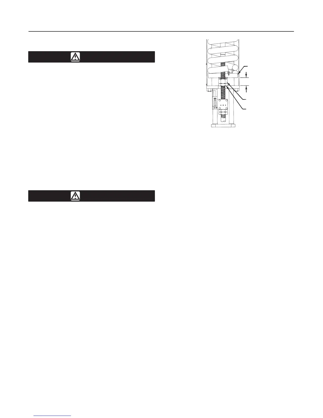
2. Measure dimension B as shown in figure 3. Cut
length of spacers as follows:
a. If it is desired to decrease spring compression,
make the spacers approximately 3/16-inch (4.8
mm) longer than dimension B.
b. It it is desired to increase spring compression,
make the spacers approximately 3/16-inch (4.8
mm) shorter than either dimension B plus the
amount of adjustment required or dimension B plus
valve travel, whichever is less.
3. Whenever the total amount of adjustment required
is greater than valve travel, the adjustment must be
made in two or more steps, and the amount of adjust-
ment taken in each step must be less than valve travel.
Figure 3. Dimension B for Spring Adjustment
50A2627-C
A1007-1 / IL
SPRING SEAT
ADJUSTING NUT
JAM NUT
B
4. Pressure the actuator to attain full travel. Cautious-
ly insert the spacers at equal intervals around the
spring seat (key 19, figure 7). Spacers must be seated
squarely, or they may slip out of position. Keeping
hands and tools away from the spring and spring seat,
slowly decrease loading pressure until the spring force
holds the spacers firmly between the spring seat and
bottom of the yoke.
5. Loosen the jam nut. The adjusting nut can now be
rotated counterclockwise (when viewed from the dia-
phragm casings) to increase the loading pressure re-
quired to start actuator stem travel or clockwise to de-
crease the pressure required to start travel.
6. Pressure the actuator to move the spring seat away
from the spacers, and carefully remove the spacers.
7. Slowly reduce the air pressure to the actuator.
Make sure that the thrust bearing (key 86) is correctly
seated in the spring seat before contact with the ad-
justment nut (key 25) is made.
8. If the total adjustment required was greater than
valve travel, repeat the procedure. It will be necessary
to make new spacers using the new dimension B and
the remaining adjustment required or valve travel,
whichever is less. Tighten the jam nut when adjust-
ment is complete.
Actuator parts are subject to normal wear and must be
inspected and replaced when necessary. The frequen-
cy of inspection and replacement depends on the se-
verity of service conditions. Because of the care
Fisher Controls takes in meeting all manufacturing re-
quirements (such as heat treating and dimensional
tolerances), use only replacement parts manufactured
or furnished by Fisher Controls.
 Loading...