Type 667 Sizes 80 & 100
8
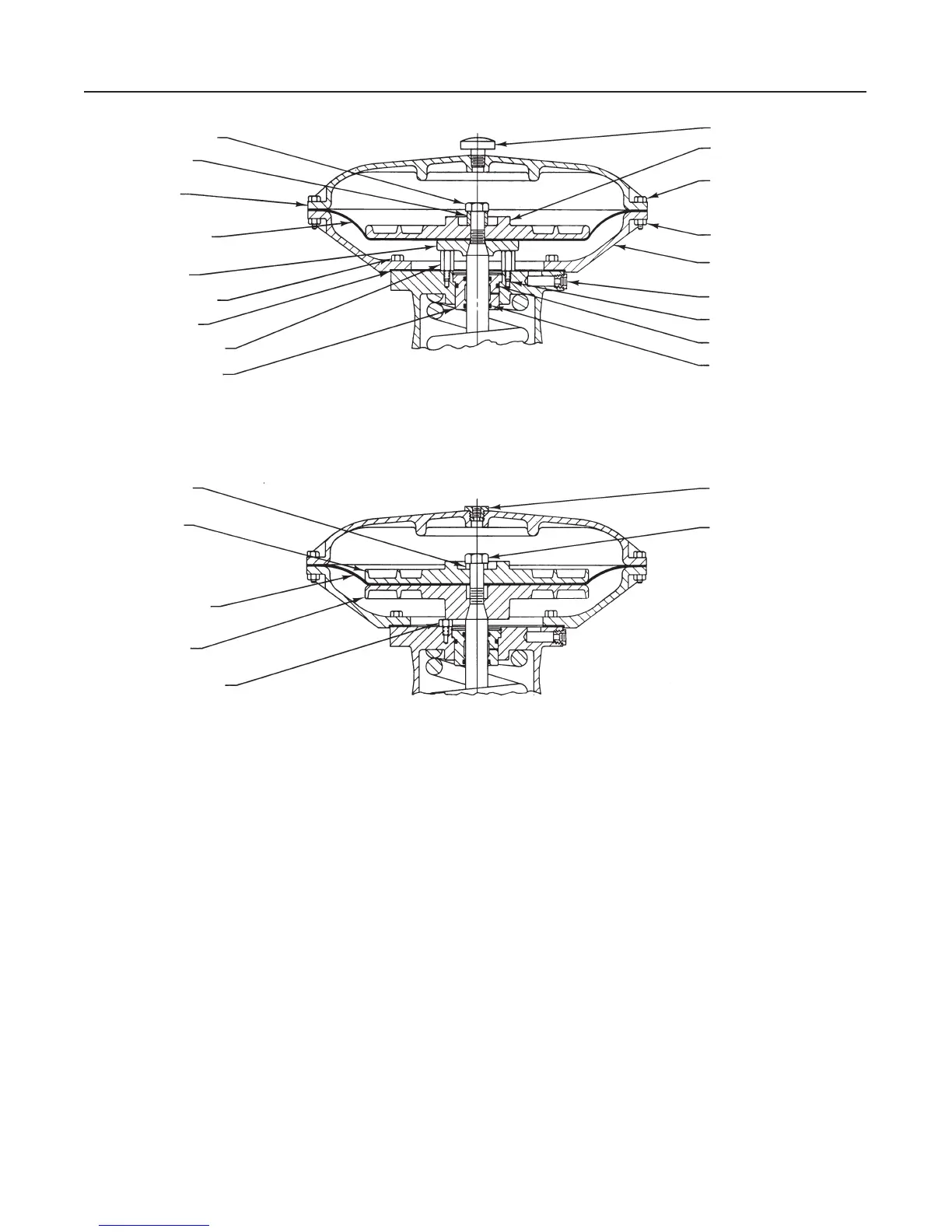
Figure 4. Size 80 Actuator Construction
CAP SCREW (KEY 12)
SPACER (KEY 2)
UPPER DIAPHRAGM
CASE (KEY 1)
DIAPHRAGM (KEY 3)
LOWER DIAPHRAGM
PLATE (KEY 71)
CAP SCREW (KEY 30)
GASKET (KEY 70)
TRAVEL STOP (KEY 84)
SEAL BUSHING (KEY 7)
VENT ASSEMBLY (KEY 17)
UPPER DIAPHRAGM
PLATE (KEY 4)
CAP SCREW (KEY 13)
HEX NUT (KEY 14)
LOWER DIAPHRAGM
CASE (KEY 64)
PIPE BUSHING (KEY 92)
SNAP RING (KEY 72)
O-RING (KEY 9)
O-RING (KEY 8)
SPACER (KEY 2)
UPPER DIAPHRAGM
PLATE (KEY 4)
DIAPHRAGM (KEY 3)
LOWER DIAPHRAGM
PLATE (KEY 71)
TRAVEL STOP (KEY 84)
PIPE BUSHING (KEY 78)
CAP SCREW (KEY 12)
50A8597-D
50A8599-C
C0772 / IL
16. Once completed, no more tightening is recom-
mended.
17. For size 80 actuators without a manual operator,
slide the following parts over the bottom of the stem;
yoke bushing holder (key 250), two split yoke bushings
(key 249), and yoke bushing retainer (key 251). Se-
cure into place with 4 cap screws (key 252). Before
inserting bushing halves, lightly coat with Lubriplate
MAG-1 (key 237) or an equivalent lubricant.
18. Mount the actuator on the valve in accordance
with the procedures in the
Installation
section.

 Loading...