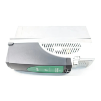
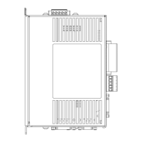
Section 3– Page 19
Table 3-H – Power Connector
Conn # Signal Signal Description
22 MOTOR GND Chassis ground motor side. Connected internally to the Earth ground
terminal.
23 MOTOR
PHASE R
Motor power phase R.
24 MOTOR
PHASE T
Motor power phase T.
25 MOTOR
PHASE S
Motor power phase S.
26 -DC BUS High power negative DC voltage.
27 + DC BUS High power positive DC voltage.
28 INT SHUNT This terminal pin is linked with terminal pin #27 to enable the internal
brake resistor (default). If an external shunt is required, disconnect
this internal shunt resistor by removing the link between terminals 27
and 28. See the “Special Applications” section.
29 EXT SHUNT This terminal is used to drive an external brake resistor instead of
the internal one. The external brake resistor will be connected
between this terminal pin and pin#27. If an external shunt is
required, disconnect this internal shunt resistor by removing the link
between terminals 27 and 28. See Chapter 6.
30 AC LINE 1 Phase 1 of the AC line.
31 AC LINE 2 Phase 2 of the AC line.
32 AC LINE 3 Phase 3 of the AC line.
33 EARTH GND Chassis ground power supply side. This is not connected to the logic
side common. It is connected to the amplifier frame.
Artisan Scientific - Quality Instrumentation ... Guaranteed | (888) 88-SOURCE | www.artisan-scientific.com
 Loading...