5 • MultiFlex ESR I&O Manual 026-1720 Rev 4 06-APR-2010
6 Software Overview
The MultiFlex ESR board is intended to inter-
face closely with E2’s Standard Circuit applica-
tion. Once a valve on the MultiFlex ESR board
has been associated with a Standard Circuit, the
Standard Circuit assumes control of the valve’s
position. The Standard Circuit must be specifi-
cally configured to control a MultiFlex ESR
valve so that the advanced capabilities provided
with the MultiFlex ESR will be enabled.
Valve Rescaling
The Standard Circuit has an enhanced control
strategy when it is configured to control a Multi-
Flex ESR valve. As with previous ESR control,
a PID algorithm is used to position the valve
during refrigeration mode in order to maintain
the circuit temperature setpoint. In addition, a
minimum and maximum valve percentage may
be specified. When this is used, the PID output
(0-100%) is rescaled to a control range between
the minimum and maximum valve percentage
parameters. This may be useful in situations
where the valve is slightly oversized and tends to
continuously overshoot the temperature setpoint.
Pulldown Mode
A new Standard Circuit control state named
Pulldown has been added. The Pulldown state is
optional and is, by default, disabled. When
enabled, the Standard Circuit will go into Pull-
down following a defrost cycle or a case wash.
Also, if a door switch is configured and refriger-
ation mode is temporarily suspended due to the
door opening (such as with a walk-in box), a
Pulldown will be initiated when the door closes.
The Pulldown mode simply forces the valve to a
fixed position, as specified with the Pulldown
Percent parameter. The circuit will stay in Pull-
down until the case temperature reaches the set-
point or the maximum time allowed in Pulldown
has been exceeded. The maximum time in Pull-
down defaults to zero, which disables the Pull-
down mode. By setting this to a valid time (up to
2 hours), Pulldown mode will be enabled.
Valve Failsafe
The Standard Circuit has additional valve fail-
safe capability. If a control failure occurs, such
as a loss of the control temperature sensor, the
valve will be instructed to go to a failsafe posi-
tion. As with previous ESR control, the valve
may be configured to go to a fixed position, as
specified by the Temp Fail EEPR % parameter.
However, a new Valve Daily Average Position is
now being calculated for MultiFlex ESR and
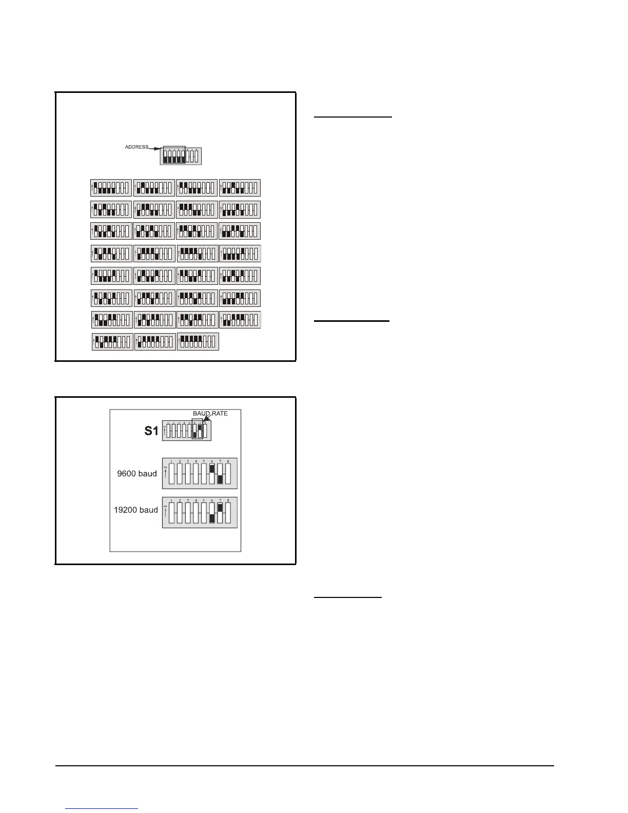
Figure 5-1 - Network Address Settings
Figure 5-2 - Baud Rate Settings
S1
Set the network address
using the first 5 rockers
of dip switch S1.
Valid address range 1-31.
2345678
1
ON
2345678
1
ON
2345678
1
ON
2345678
1
ON
BOARD 1 BOARD 2 BOARD 3 BOARD 4
2345678
1
ON
23456 78
1
ON
2345678
1
ON
2345678
1
ON
BOARD 5
BOARD 6 BOARD 7 BOARD 8
2345678
1
ON
2345678
1
ON
2345678
1
ON
2345678
1
ON
BOARD 9 BOARD 10 BOARD 11 BOARD 12
2345678
1
ON
23456 78
1
ON
2345678
1
ON
2345678
1
ON
BOARD 13 BOARD 14 BOARD 15 BOARD 16
2345678
1
ON
23456 78
1
ON
2345678
1
ON
2345678
1
ON
BOARD 17 BOARD 18 BOARD 19 BOARD 20
2345678
1
ON
23456 78
1
ON
2345678
1
ON
BOARD 21 BOARD 22 BOARD 23
2345678
1
ON
BOARD 24
2345678
1
ON
23456 78
1
ON
2345678
1
ON
2345678
1
ON
BOARD 25 BOARD 26 BOARD 27 BOARD 28
2345678
1
ON
BOARD 29
2345678
1
ON
23456 78
1
ON
BOARD 30
BOARD 31
 Loading...