MultiFlex ESR Molex Connector Board (Discontinued) Installation • 2
1.2. MultiFlex ESR Molex Connec-
tor Board (Discontinued)
2 Installation
The MultiFlex ESR control board is designed to
be located in a central location, preferably near
the valves it is driving. Figure 2-1 shows the
mounting dimensions of the MultiFlex ESR
board:
2.1. Panel Mounting and Heat Dis-
sipation
The MultiFlex ESR can generate a substantial
amount of heat when it draws up to a maximum
of 80 VA during operation. The MultiFlex ESR
is rated for a maximum ambient temperature of
65°C (150°F); therefore, depending on the size
of the enclosure and what other devices are in
that enclosure with the MultiFlex ESR, you may
need to ventilate the enclosure by installing air
circulation fans or other devices to aid in heat
dissipation.
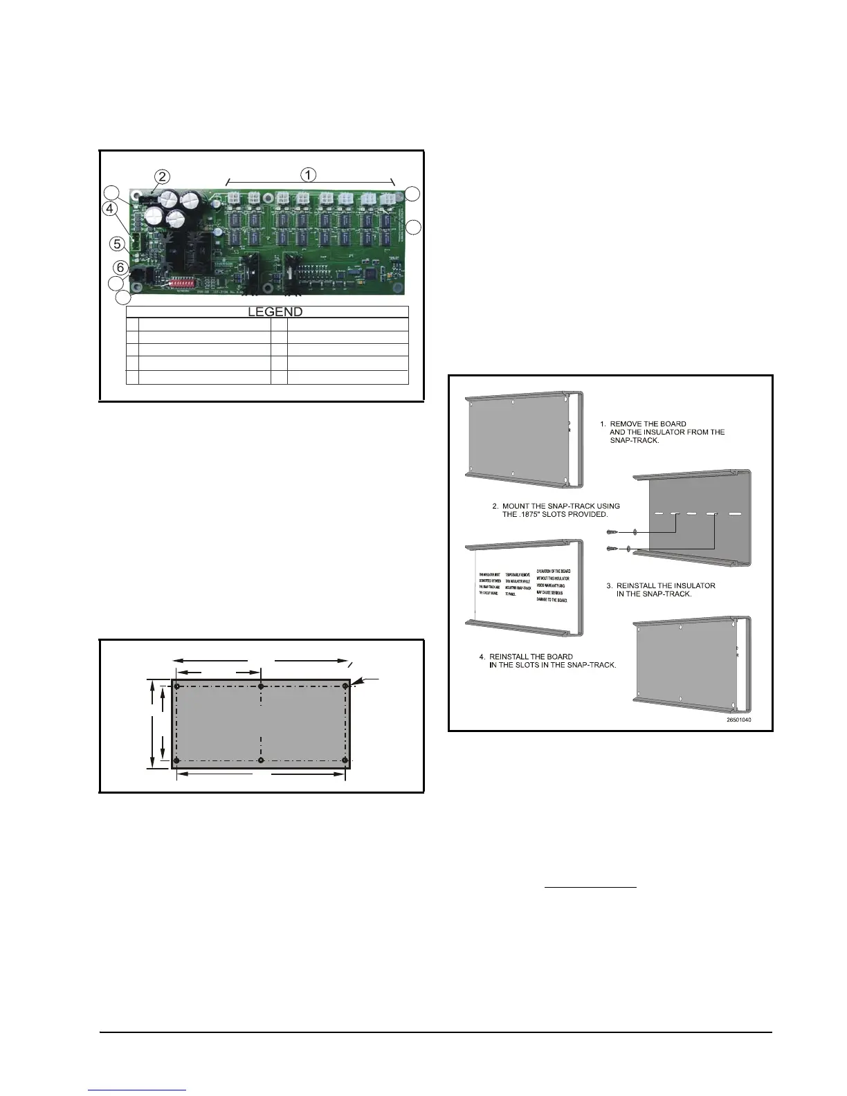
2.2. Snap-Track Installation
Boards not supplied with an enclosure are sup-
plied with a snap-track for easy installation. The
insulation sheet and I/O board must be removed
from the track before the track is mounted. The
snap-track is mounted using the 0.1875” mount-
ing slots. Figure 2-2 shows this installation pro-
cedure:
3 Wiring
3.1. Power
Each MultiFlex ESR board requires a Class 2,
80VA 24VAC center-tapped
transformer for
power. The power connector (labeled J12) is
located in the top left corner of the board.
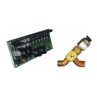
Figure 1-2 - MultiFlex ESR Molex Connector Board Layout -
Discontinued (P/N
810-3198)
Figure 2-1 - MultiFlex ESR Board Dimensions
24VAC CT 75 VAC Power Input
Valve Connectors (8)
I/O Network Input
Termination Jumpers
Network Address Switches
General Status LED
1
5
2
3
4
6
7
8
HHT Jack
TX and RX LEDs
8
3
7
9
10
Open LED (8)
Close LED (8)
9
10
3.5”
4.00”
10.00"
4.75”
TYP 2 PL
MULTIFLEX ESR BOARD
WEIGHT: 9.4 OZ.
O 0.220”
TYP 6 PL
9.5”
Figure 2-2 - MultiFlex ESR Snap-Track Installation