106 Chapter 7 Alarm Handling
No. Alarm Handling method
8 Rect Failure
The red LED on the rectifier will turn on
1. Reset the rectifier by powering it off and then on again
2. If the rectifier still causes this alarm, replace it
9 Rect Protect
Check if the mains is outside the range of 80V ~ 295V (between the AC under-voltage point and over-
voltage point)
If the power supply is constantly over/under-voltage, the mains power network should be improved
10 Rect Fan Fails
1. Check whether the rectifier fan is still working.
2. If the fan stands still, pull out the rectifier to check whether the fan is blocked or not. If yes, clean it
and push the rectifier back. However, if the fan still does not move after the rectifier is powered on,
replace it (see Replacing rectifier fan in 6.2 Handling Rectifier Fault)
11
Rect Not
Respond
Check if the communication between rectifier and monitoring module fails. If the communication is
normal, reset the rectifier by pulling it out and pushing back in. If the alarm persists, replace the rectifier
12 Batt Over Temp
1. Check if there is battery internal fault. If yes, replace the fault battery
2. Check if the battery room temperature too high. If yes, cool down the battery room
7.2 Handling Rectifier Fault
The indicator description and handling methods of R48-1800 rectifier, R48-2900U rectifier and R48-3200 rectifier are
the same.
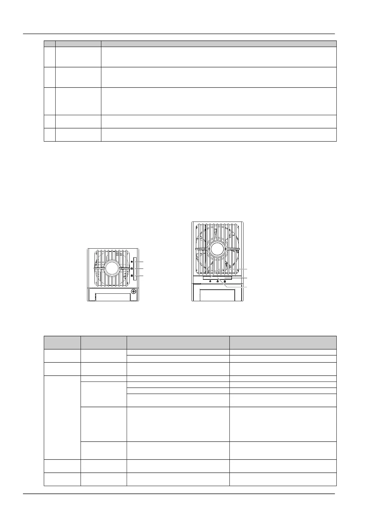
Handling indicator fault
The symptoms of usual rectifier faults include: Run indicator (green) off, Protection indicator (yellow) on, Protection
indicator blink, Fault indicator (red) on and Fault indicator blink, as shown in Figure 6-1.
Figure 1.1 Rectifier indicator
The indicators are shown in Figure 6-2.
Table 1.2 Indicator fault description
Symptom
Monitoring module
alarms
Causes Handling method
Run indicator
off
No alarm
No input/output voltage Make sure there is input/output voltage
Assistant power source of the rectifier fails Replace the recitifier
Run indicator
blinks
No alarm
The monitoing module performs operations
upon the rectifier
No actions need to be taken
Protection
indicator on
Rect Protect AC input voltage abnormal Make sure the AC input voltage is normal
Rect Protect
Fan blocked Remove the object that blocks the fan
Ventilation path blocked at the inlet or vent Remove the object at the inlet or vent
Ambient temperature too high or the inlet too
close to a heat source
Decrease the ambient temperature or remove
the heat source
Load share Alarm Current sharing imbalance
Check whether the rectifier communication is
normal. If not, check whether the
communication cable is in normal connection.
If the communication is normal while the
protection indicator is on, replace the rectifier
Rect Protect
Power factor compensation internal under
voltage or over voltage
Replace the rectifier
Protection
indicator blinks
Rect Not Respond Rectifier communication interrupted
Check whether the communication cable is in
normal connection
Fault indictor
on
Rect HVSD Rectifier over-voltage
Reset the rectifier. If the protection is triggered
again, replace the rectifier
NetSure 501 A50, NetSure 501 AA0, NetSure 701 A51 19-Inch Subrack Power Supply System User Manual
 Loading...