Connector Board
Rectifier Unit
-48V
0V
KM1
Multifunction Unit
1QF1
Shunt
Monitor
Monitor Back Board
CAN
KM2
NPL
1QFx 2QFx2QF1
QD1
Bat.1
Rect.9 Rect.10
3QF1 3QF2
3QF3
3QFx
PL
NPL
NPL
PL
0V
0V
4QF1
5QF1 5QFx
Signal Board
4QFx
PD3
230VAC 230VAC
PD4
to PD2
L2L1 L3
N
PE Bar
to 0V
N Bar
QF1
Signal Board
SPD
RB
Bat.2
QD2
QD3
Bat.3
4QF3
4QF2 5QF2
5QF3
Distribution Unit
Rect.8
230VAC
Rect.7
230VAC
Rect.6
230VAC
Rect.5
230VAC
Rect.4
230VAC
Rect.3
230VAC
Rect.2
230VAC
Rect.1
230VAC
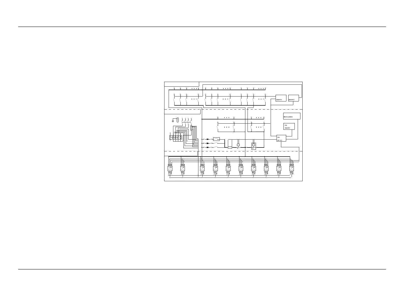
1. The AC distribution has 3 schemes, determined by user requirement. Refer to diagram (2).
2. The maximum output current of the MFU is 300A.
3. The number of the 1QFx and 2QFx in MFU is configurable. The total width of the load MCBs should be smaller than 190mm.
4. The DU is optional. The number of the 3QFx, 4QFx and 5QFx in MFU is configurable. The total width of the load MCBs should be smaller than the installation size.
Note:
5. The monitoring module can be M501D or M800D.
6. The number of the battery MCBs can be 2 or 3.
7. The LLVD contactor KM2 is configurable.
Figure 5 Schematic diagram of NetSure 501 AA0 (1)
NetSure 501 A50, NetSure 501 AA0, NetSure 701 A51 19-Inch Subrack Power Supply System User Manual
 Loading...