20 Chapter 4 Use Of Monitoring Module M500D
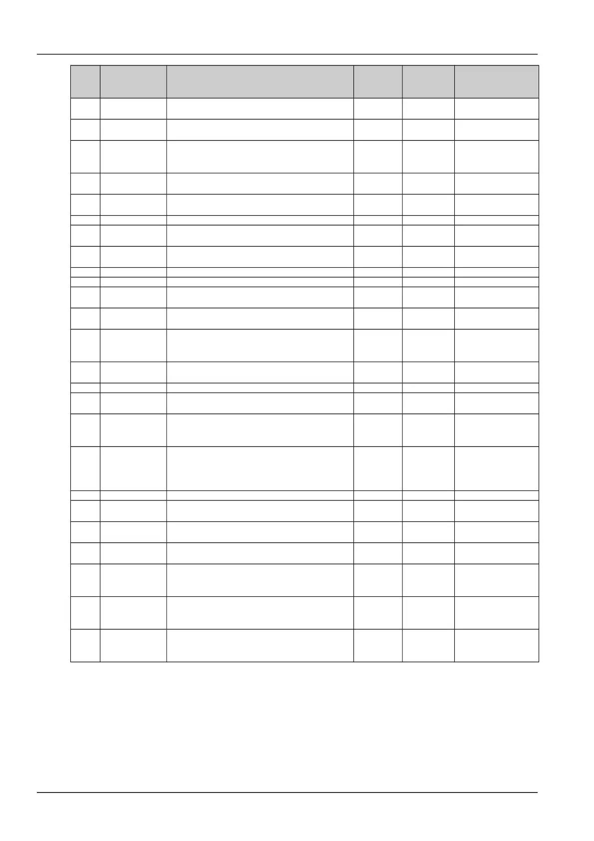
Serial
No.
Alarm Description
Default
alarm
level
Default
related
relay
Related parameter
configuration
16 Mains Failure
All the AC input voltages from the rectifier are
less than 80V
Major 1
17
AC Voltage
Low2#
AC input voltage less than “AC Low#2”. The
default for AC Voltage Low#2 is 80Vac
Observati
on
None
AC input under-
voltage alarm point
18
AC Voltage
Low1#
AC input voltage lower than the setting of “AC
Low#1”. The default for AC Voltage Low#1 is
180Vac
Observati
on
None
AC input under-
voltage alarm point
19
AC Voltage
High
AC input voltage higher than the setting of “AC
High”. The default for AC Voltage High is 280Vac
Observati
on
None
AC input over-
voltage alarm point
20 Maintain Alarm Time to maintain system
Observati
on
None
21 Self-detect Err Hardware Self-detect Error No Alarm None
22 Manual Mode Battery management is in manual control mode
Observati
on
None
23 High Load
When system reaches settable level of total
capacity. The default is 75%
24 Power Major System contains Major or Critical alarm (red LED) Critical None
25 Power Minor System contains Observation alarm (yellow LED) Critical None
26 Rectifier Lost
The controller has detected a reduction in the
number of running rectifiers
Observati
on
None
27
Multi-Rect
Alarm
More than two rectifiers alarm Critical None
28
Load share
Alarm
The output current of one rectifier is higher than
the certain value and higher than the average
value for all rectifiers
Critical None
29
Rect Not
Respond
Rectifier does not communicate with M500D Major 3
30 Rect AC Fail AC input voltage of this rectifier lower than 80V Major 3
31 Rect HVSD
This rectifier output voltage was higher than the
rectfier HVSD setting and has shut down
Major 3
32 Rect Failure
Serious load sharing alarm (the output current of
the rectifier is lower than 1A and the average load
is greater than 6A). Or rectifier’s ID repetition
Critical 3
33 Rect Protect
AC over voltage or Rectifier PFC failure or
current imbalance or Over-temperature or AC
Low voltage or AC phase loss or position pin
failure or Inner communication fault
Observati
on
3
34 Rect Fan Fails Rectifier fan fails Major 3
35 Rect Derated
Rectifier AC input voltage is low and the rectifier
internal temperature is high and high load
Observati
on
3
36 Temp Alarm
Temperature higher or Lower than the setting of
Temp,inluding Ambient temp and battery Temp
Observati
on
None
37 Batt Over Temp
Battery temperature higher than the setting of
“High Temp”, inluding temperature sensor fault
Major None
Over-temperature
alarm point
38
Digital 1 ~
Digital 6
Alarm name can be defined by users. Whether
the alarm is triggered at high voltage level or low
voltage level can be configured
No alarm 8
39
Digital7 /LVD1
Alarm
Alarm name can be defined by users. Whether
the alarm is triggered at high voltage level or low
voltage level can be configured
No alarm None
40
Digital8 /LVD2
Alarm
Alarm name can be defined by users. Whether
the alarm is triggered at high voltage level or low
voltage level can be configured
No alarm None
NetSure 501 A50, NetSure 501 AA0, NetSure 701 A51 19-Inch Subrack Power Supply System User Manual
 Loading...