48 Chapter 5 Use Of Monitoring Module M800D
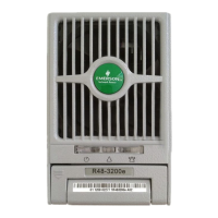
Figure 1.1 Rectifier screen 1
The signals in the screen shown in Figure 4-6 are all the actually sampled values such as “Total current”, “Average
voltage” and so on. In the screen, click the button “Control”, and the following screen pops up:
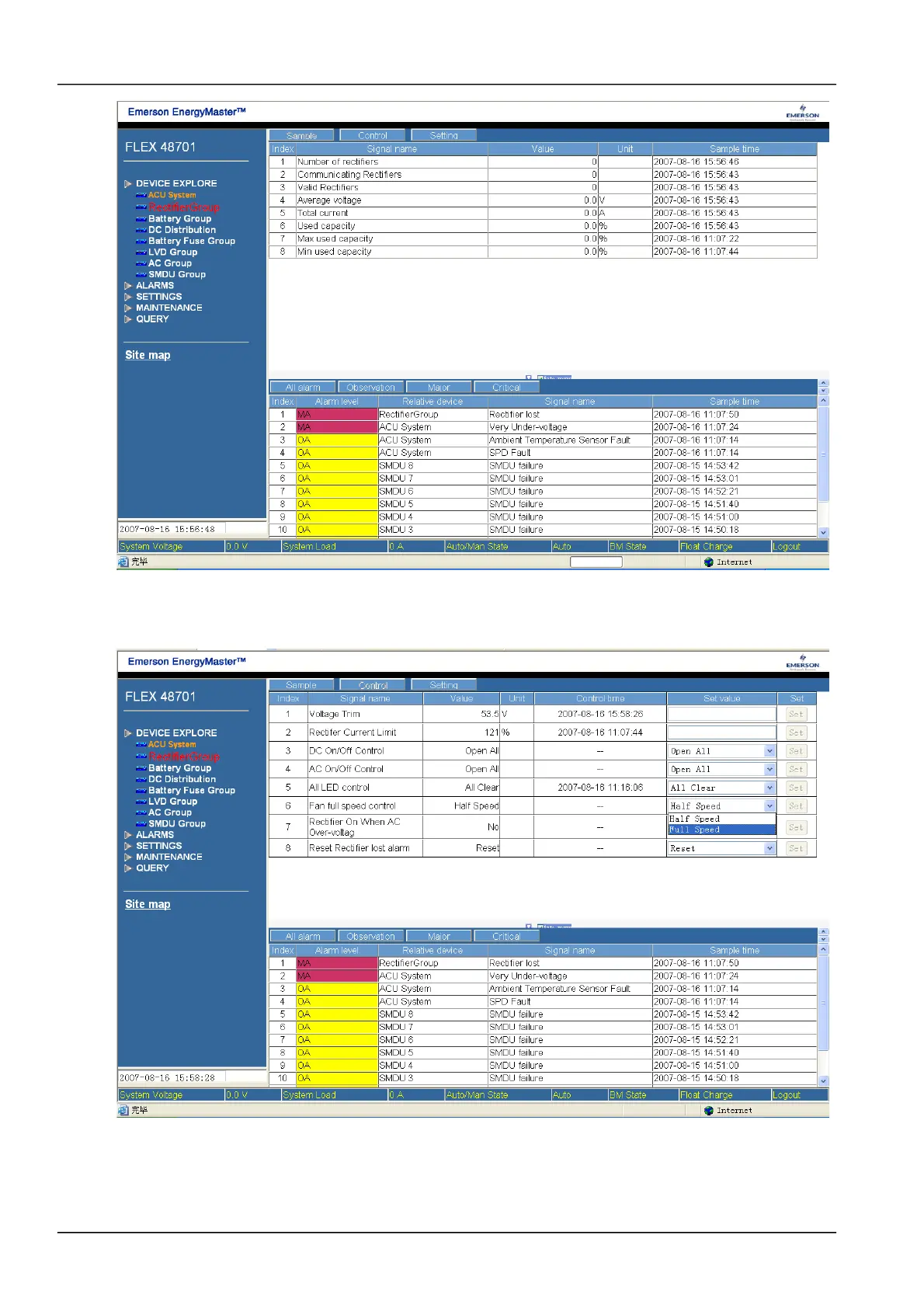
Figure 1.2 Rectifier screen 2
The signals in the screen shown in Figure 4-7 are all the values used to control the rectifier. For example, in “Fan full
speed control”, user can select “Full Speed” and click “Set” to make the rectifier fan run at full speed. The control
command is effective for all the rectifiers. Pay attention that the “Control” button is only active when the M800D is in
NetSure 501 A50, NetSure 501 AA0, NetSure 701 A51 19-Inch Subrack Power Supply System User Manual
 Loading...