10
7. Secure the light kit plate assembly to the light kit
adapter assembly by installing three 5/32-32 x
3/16” phillips head screws (supplied) into the
threaded holes in the adapter assembly
(Figure 17).
8. Install two candelabra base lamps in the sockets of
the light kit adapter plate (Figure 17):
Model CF2605 - 15-Watt Maximum
Model CF2680 - 25-Watt Maximum
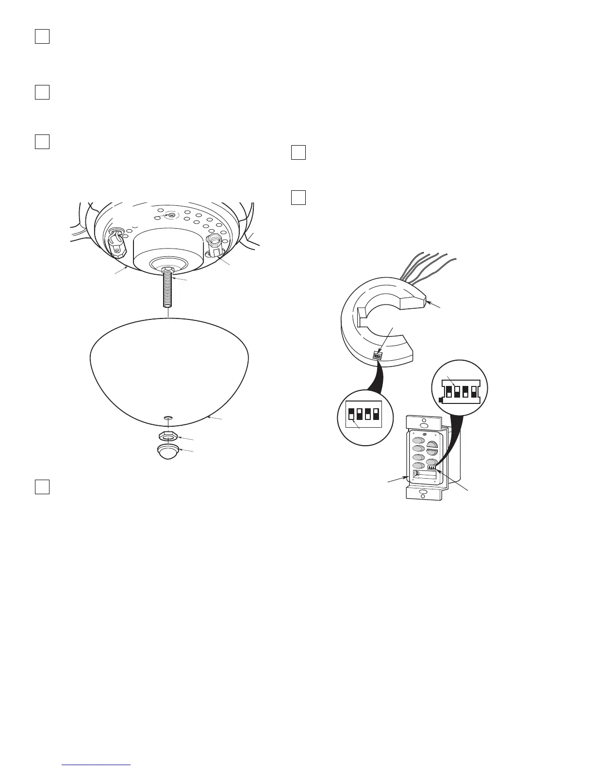
9. Position the glass shade over the threaded nipple
in the light kit plate assembly (Figure 17). Seat the
glass shade evenly over the plate assembly and
securely install the hex nut and finial nut (supplied)
on the threaded nipple.
Figure 17
10. Your ceiling fan is now installed and wired and
ready for use.
Setting Operating
Frequency of Wall Control
and Receiver (Figure 18)
Your wall control and receiver have code switches
which must be set in one of 16 possible code
combinations. The four levers (numbered 1, 2, 3, and
4) on the switches are factory-set in the ON (up)
position. Change the switch settings as follows:
1. Slide the four switch levers in the wall control to
your choice of ON (up) or down positions. Use a
ball-point pen or small screwdriver and slide the
levers firmly up or down.
2. In the receiver, slide the four switch levers to the
same positions as set in the wall control. Make
sure the levers on both switches are in the same
positions, otherwise the fan will not operate.
 Loading...