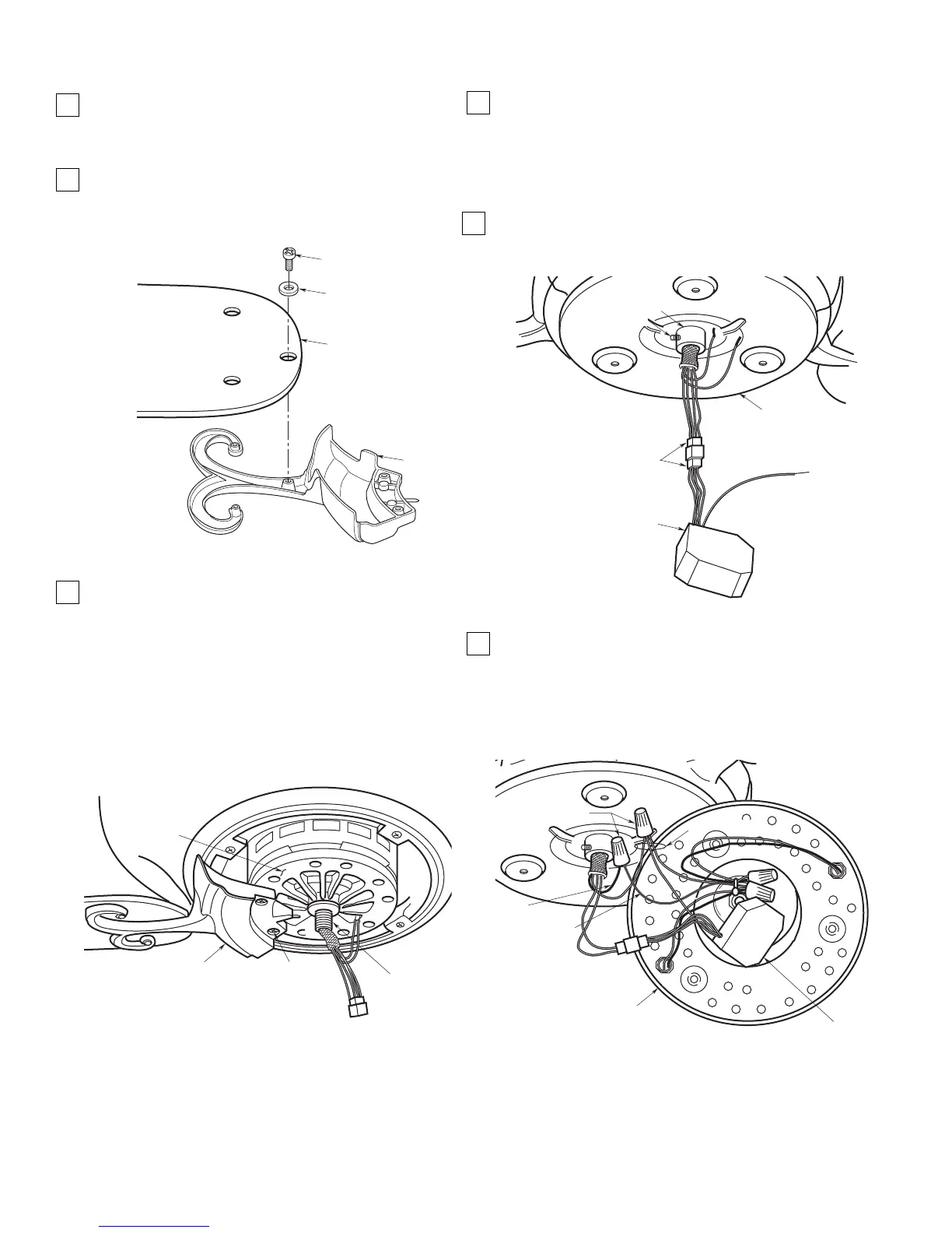
Figure 16
Final Assembly of Your Ceiling Fan
1. Use three 10-32 x 3/8” pan head screws and flat
washers (supplied) to secure the flange to the
blade (ordered separately) (Figure 13). Repeat for
the four remaining blades.
2. Use the 10 round recessed holes in the motor hub
marked with “5” and install the five blade
assemblies in accordance with Step 3.
Figure 13
3. Attach one blade assembly to the motor hub using
two 10-32 x 5/8” oval head screws (supplied) (Figure
14). Do not tighten completely at this time. Install
remaining blade assemblies in the same way. Gently
snug all flange screws to the motor hub, working
around the hub in a clockwise sequence. Next,
securely tighten all flange screws, again working in a
clockwise sequence. Failure to follow this procedure
could result in fan wobble. This completes the blade
installation.
4. Using the 5/64” hex wrench (supplied), loosen the
setscrew in the collar on the light kit adapter
assembly. Then pass the connector and the wires
from the motor shaft through the collar (Figure 15).
Screw the adapter assembly onto the motor shaft
and then tighten the setscrew to secure the adapter
assembly to the motor shaft.
5. Engage the connector from the motor shaft with the
connector from the reversing module (supplied)
(Figure 15).
6. Securely connect the black wire from the light kit
plate assembly to the blue wire from the motor shaft
using a wire connector (supplied) (Figure 16).
Connect the white wire from the plate assembly and
the white wire from the reversing module to the white
wire from the motor shaft using a wire connector
(supplied).
Figure 15
NOTE: When installing the light kit plate
assembly, position the wires, the connectors and
the reversing module in the raised center portion
of the plate assembly. Do not pinch wires between
the light kit plate assembly and the adapter
assembly.