17
A161
A162
A163
W
Y3
P5
R1
FD
Y1
Y4
Y2
A1
G
C
P
E1
E2
E3
A3A2 P3P2P1
P
D1
GG
P
D3D2
H
B
MB
P4
MH
t
E3
H
B
A160
E1 E2
A1 A2
GG
P1
D1 D2
P2
D3
P3
A3
GY4
A
PR
D
Y1
P
A
MB
P4
P5
MH
A
Y3
P
PA
Y2
FR1
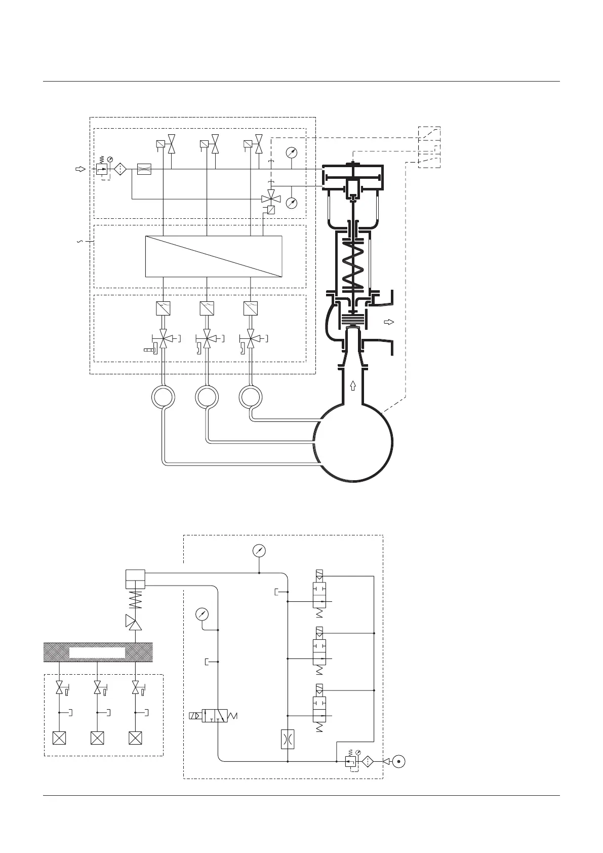
SEMPELL SERIES STE 4 CONTROL DEVICE FOR SAFETY VALVES
Operating instructiOns
IMPULSE UNIT A161
SYSTEM CIRCUIT DIAGRAM
Air supply
Power
supply
Pneumatic
control unit
Electrical
switching unit
Pressure
Travel
System pressure
Pulse generating
unit
Pneumatic control unit A163
Loading air
Compressed-air supply
Lifting air
Safety valve
Pulse generating unit A161
System
NOTES
E1 - E3 Pressure sense line
A1 - A3 Shut-off valve
D1 - D3 Pressure switch
C Key
G Valve interlock
P1 - P5 Test connection
D Throttle
F Filter
B Cavity for loading
H Cavity for lifting
Y1 - Y3 Solenoid valve (closed-circuit principle)
Y4 Solenoid valve (open-circuit principle)
MB Pressure gauge for loading
MH Pressure gauge for lifting (easing)
R1 Pressure control valve
A160 Pneumatic actuator