18
"Z"
E3
R2
D
S
H
B
A160
E1 E2
A1 A2
GG
P1
D1 D2
P2
D3
P3
A3
GY4
A
PR
Y1
PA
MB
P4
P5
MH
A
Y3
P
PA
Y2
R1 F
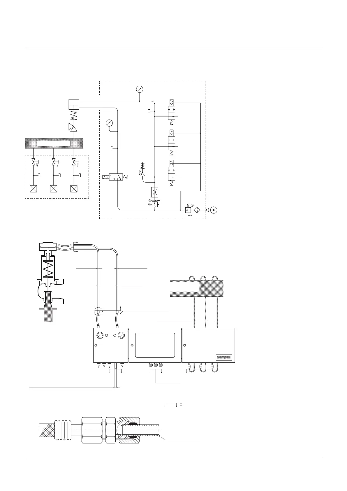
SEMPELL SERIES STE 4 CONTROL DEVICE FOR SAFETY VALVES
Operating instructiOns
SYSTEM CIRCUIT DIAGRAM
Design with pressure regulator R2 for increased lifting air pressure
SYSTEM CIRCUIT DIAGRAM
Pneumatic control unit A163
Loading air
Compressed-air
supply
Loading
Lifting
ø22 x 2 Pipe
Compressed air hose ø19 mm
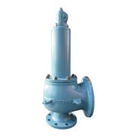
Safety valve
Pipe ø22 x 2 on site
Detail “Z”
System
pressure
Sense line
Scope of supply
Air exhaust
Compressed air supply connection pipe ø22 x 2
Main supply
Lifting air
Safety valve
Pulse generating unit A161
System
NOTES
E1 - E3 Pressure sense line
A1 - A3 Shut-off valve
D1 - D3 Pressure switch
C Key
G Valve interlock
P1 - P5 Test connection
D Throttle
F Filter
B Cavity for loading
H Cavitye for lifting
Y1 - Y3 Solenoid valve (closed-circuit principle)
Y4 Solenoid valve (open-circuit principle)
MB Pressure gauge for loading
MH Pressure gauge for lifting (easing)
R1, R2 Pressure control valve
A160 Pneumatic actuator
S Safety valve