ER5000 —
157
The ERTune™ Program: Basic Features
5. If there is offset, move the Maximum slider slightly to the right,
to increase the level of positive Integral that will be allowed
to accumulate.
6. Repeat until the offset is eliminated.
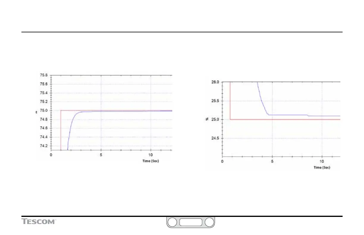
Figure 58: Typical Tuning: Offset Corrected
Even at a high level of magnication, there is now no offset between setpoint and
feedback.
7. When you are satised with the response at Setpoint 2,
return to default zoom in the Plot Screen. Then zoom in
closely at the level of Setpoint 1 (25%).
8. Look closely for offset between the setpoint and feedback
level once the system reaches stable state. If there is offset,
move the Minimum slider slightly to the left, to increase the
level of negative Integral that will be allowed to accumulate.
9. Repeat until the offset is eliminated.
Figure 59: Typical Tuning: Checking for Offset at Setpoint 1
As was true for Setpoint 2, some offset correction will be required at Setpoint 1.
10. When you are satised with the response at Setpoint 1, return
to default zoom in the Plot Screen. Toggle between the two
setpoints and note stability, accuracy and response time.
(continued next page)

 Loading...

