Unidrive M300/HS30 Quick Start Guide 9
Issue Number: 6
Table 2-2 Adaptor Interface (AI) option module identification
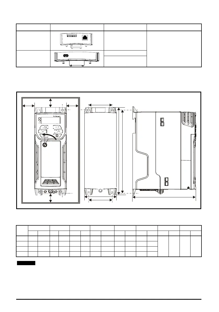
3 Mechanical installation
The drives can be panel mounted with 0 mm space between the drives. For further information on
mechanical installation refer to the Drive User Guide.
To remove the terminal cover, use a flat bladed screwdriver to rotate the terminal cover locating clip
by approximately 30° in a counter clockwise direction, and then slide the cover down.
Type Option module Name Further Details
Communications AI-485 Adaptor
See Drive User Guide
Backup
AI-Backup Adaptor
AI-Smart Adaptor
Drive
Size
HWD M1M2∅ AB*
mm in mm in mm in mm in mm in mm in mm in mm in
1 160 6.30 75 2.95 130 5.12 143 5.70 53 2.08 5 0.2
0 0.00 100 3.93
2 205 8.07 78 3.07 150 5.91 194 7.63 55 2.17 5 0.2
3 226 8.90 90 3.54 160 6.30 215 8.46 70.7 2.80 5 0.2
4 277 10.91 115 4.53 175 6.89 265 10.43 86 3.40 6 0.23
A minimum clearance of 100 mm above and below Frame 01 to 04 products is required
for applications where the product is subjected to rated load and rated ambient
temperature.
A
W
M2
M2
B
D
B
A
HM1
Cover
release
Unidrive M300 Quick Start Guide English Iss6.book Page 9 Tuesday, September 22, 2015 3:21 PM

 Loading...


