Unidrive M702 / HS72 Control Getting Started Guide 33
Issue Number: 2
Safety information Introduction Control connections Getting started
Basic parameters
(Menu 0)
Running the motor
Further information
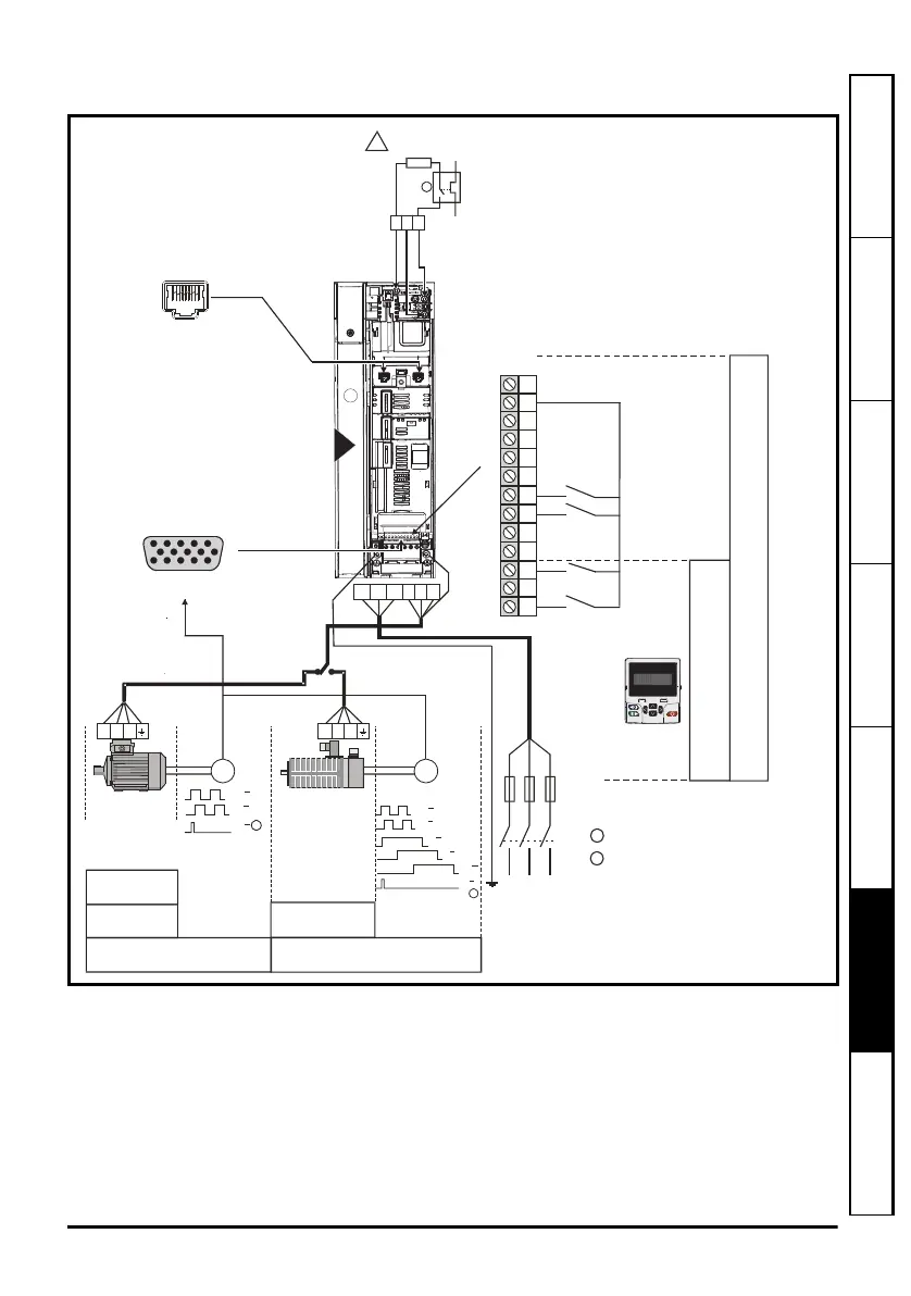
Figure 6-1 Minimum connections to get the motor running in any operating mode (size 4
illustrated)
* Ethernet fieldbus communication ports.
** Position feedback port (refer to Table 3-1 P1 position feedback connection details on page 9).
AA
BB
UU
VV
WW
ZZ
1
AA
BB
ZZ
1
E E
Induction
motor
RFC-S
1
2
Marker pulse optional
Thermal overload for braking resistor
to protect against fire risk. This must be
wired to interrupt the AC supply in the
event of a fault. This is not required if the
optional internal braking resistor is used
T
e
r
m
i
n
a
l
M
o
d
e
K
e
y
p
a
d
M
o
d
e
Communications
port*
Keypad
Optional item, must
be installed
for keypad mode
L1 L2 L3
Fuses
L1 L2 L3
U
VW
UVW
Servo motor
(permanent
magnet)
2
!
+
_
BR
Braking resistor
(optional)
Position feedback
connector 15 way D-type**
5
10
15
1
6
11
UVW
RFC-A
Open loop
4
RUN FWD
RUN REV
10
11
8
9
6
7
4
5
3
24V
2
1
SAFE TORQUE
OFF 1
12
13
SAFE TORQUE
OFF 2
RFC-A
Sensorless
RFC-A
Sensorless
Unidrive M702_HS72 Control GSG Iss2.book Page 33 Friday, December 12, 2014 1:05 PM
 Loading...


