Safety
information
Product
information
Mechanical
installation
Electrical
installation
Getting
started
Basic
parameters
Running the
motor
Optimization NV Media Card
Advanced
parameters
Diagnostics UL Listing
Unidrive M100 / M101 Control User Guide 9
Issue Number: 1
2.4 Operating modes
The drive is designed to operate in any of the following modes:
1. Open loop mode
Open loop vector mode
Fixed V/F mode (V/Hz)
Square V/F mode (V/Hz)
2.4.1 Open loop mode
The drive applies power to the motor at frequencies varied by the user. The motor speed is a result of the output frequency of the drive and slip due
to the mechanical load. The drive can improve the speed control of the motor by applying slip compensation. The performance at low speed depends
on whether V/F mode or open loop vector mode is selected.
Open loop vector mode
The voltage applied to the motor is directly proportional to the frequency except at low speed where the drive uses motor parameters to apply the
correct voltage to keep the flux constant under varying load conditions.
Typically 100 % torque is available down to 1 Hz for a 50 Hz motor.
Fixed V/F mode
The voltage applied to the motor is directly proportional to the frequency except at low speed where a voltage boost is provided which is set by the
user. This mode can be used for multi-motor applications.
Typically 100 % torque is available down to 4 Hz for a 50 Hz motor.
Square V/F mode
The voltage applied to the motor is directly proportional to the square of the frequency except at low speed where a voltage boost is provided which is
set by the user. This mode can be used for running fan or pump applications with quadratic load characteristics or for multi-motor applications. This
mode is not suitable for applications requiring a high starting torque.
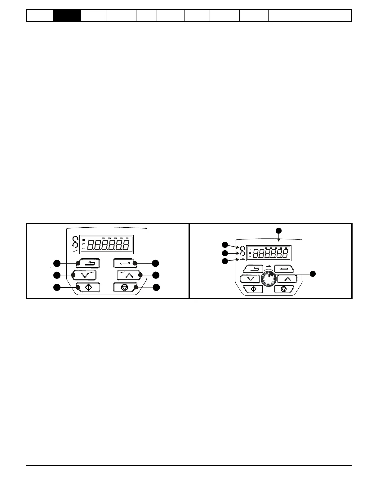
2.5 Keypad and display
The keypad and display provide information to the user regarding the operating status of the drive and trip codes, and provide the means for changing
parameters, stopping and starting the drive, and the ability to perform a drive reset.
(1) The Enter button is used to enter parameter view or edit mode, or to accept a parameter edit.
(2 / 5) The Navigation button can be used to select individual parameters or to edit parameter values.
(3) The Stop / Reset button is used to stop and reset the drive in keypad mode. It can also be used to reset the drive in terminal mode.
(4) The Start button is used to start the drive in keypad mode.
(6) The Escape button is used to exit from the parameter edit / view mode.
(7) The Speed Reference Potentiometer is used to control the speed reference in keypad mode (only on Unidrive M101).
(8) Units.
(9) Run forward indicator.
(10) Run reverse indicator.
(11) Keypad reference indicator.
Figure 2-2 Unidrive M100 keypad detail Figure 2-3 Unidrive M101 keypad detail

 Loading...


