LIST OF ILLUSTRATIONS
Page No.
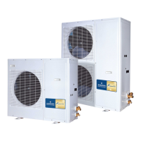
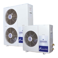
Fig.1 ZX Single Fan Unit (ZX200, ZX300 & ZX400) 5
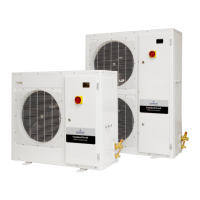
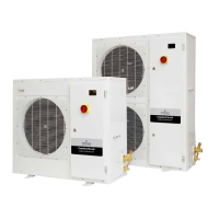
Fig.2 ZX Dual Fan Unit ( ZX 500, ZX600 & ZX 750) 6
Fig.3 E2 Control Board 7
Fig.4 The Defrost Module 8
Fig.5 The Diagnostic Module 8
Fig.6 The Diagnostics Interpretation Chart 10
Fig.7 ZX Nomenclature 14
Fig.8 ZX 600 TFD (with front panel open to expose the components) 16
Fig.9 Fan and Fan Motor exposed 17
Fig.10 Location of the Fixed High and Low Pressure Switches 17
Fig.11 Liquid Injection System 18
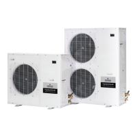
Fig 12 3 –Dimensional View 19
Fig.13 Physical Dimensions 21/22
Fig.14 Four Port Charging Manifold 23
Fig 15 Electronic Vacuum Gauge 24
Fig 16 Commisioning Hook-Up and Essential Equipment 27
Fig 17 Schraeder Valves with and without depressors 28
Fig 18 E2 Unit Controller Board – Layout and Major Components 35
Fig 19 E2 Control Reference Guide 38
Fig 19 Diagnostic Module details 40
Fig 20 Defrost Module details 42
Fig 21 Defrost Module Settings 42
Fig 22 E2 Board connected to the Modules 43
3
 Loading...