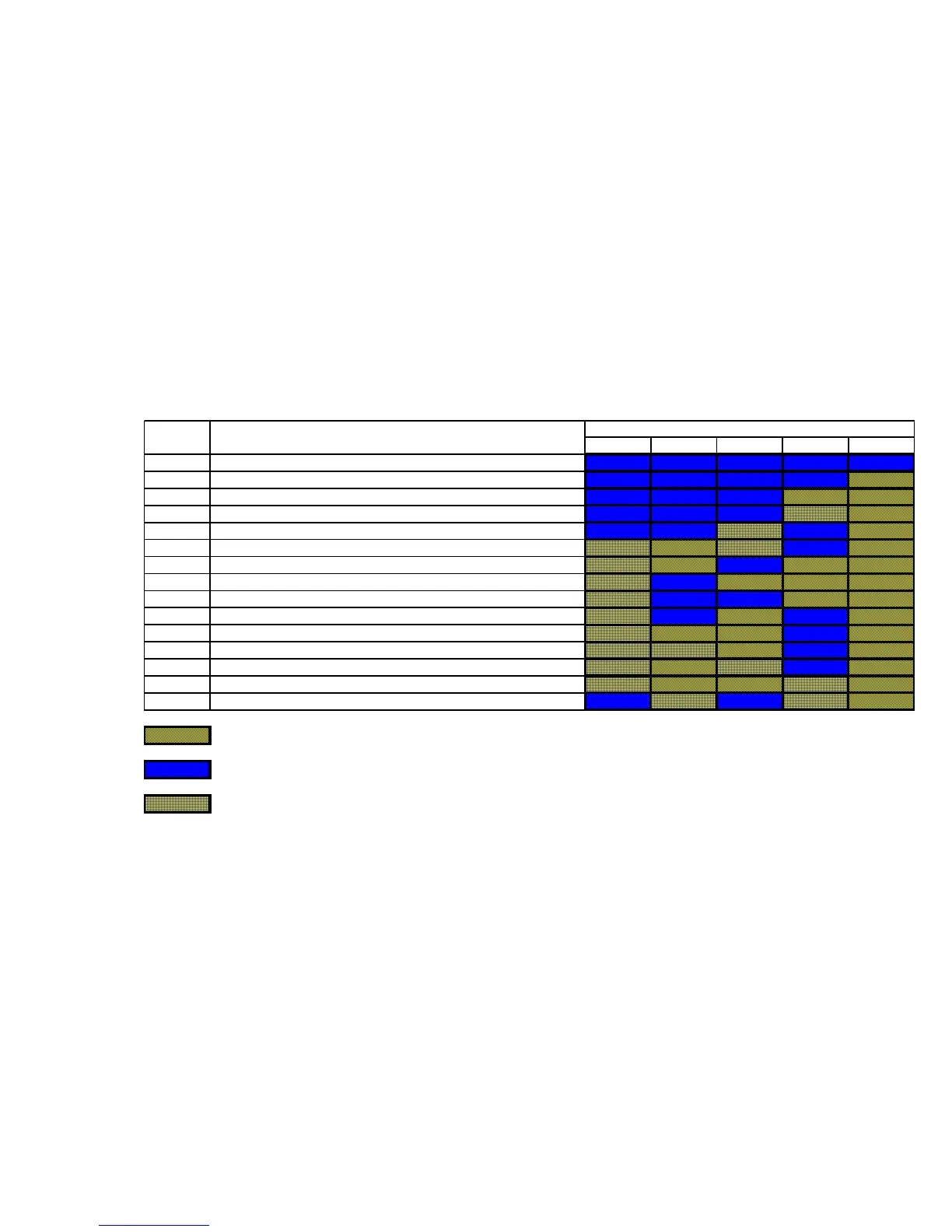
2.4 Diagnostic and Defrost Features
The Diagnostic Module (Option) is also installed within the Chassis and has a 5 LED’s (Light
Emitting Diodes ) that can either be ON, OFF or BLINKING. The Combination of these 5 LED’s
with these 3 different LED status can provide the different system status as shown in Fig 6 below :
Fig 6. The Diagnostics Interpretation Chart
Status Event LED Status
D1 D2 D3 D4 D5
Normal Unit OFF/Phase 'U' or 'N' missing
Normal Power ON
Normal Compressor ON
Normal Fresh Start/Normal Start
Normal Defrost ON
Fault DLT Overlimit
Fault Ambient sensor failure
Fault MCT sensor failure
Fault DLT Thermistor failure
Fault HP Cut Out
Fault Compressor Over Current
Fault Compressor Incorrect Phase sequence
Fault Compressor Voltage Imbalance
System Liquid Floodback
Fault Compressor about to turn ON & Ambient sensor failure
On DLT Discharge Line Temperature
MCT Mid Coil Temperature
Off
Blink
Warning
10
 Loading...