13
6 Technical description
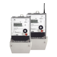
6.1 Technical data
3x230/400 V, 3x220/380 V, 3x58/100 V, 3x63/110 V,
3x115/200 V, 3x127/220 V, 3x132/230 V
5(60) A, 5(85) A, 5(100) A, 10(60) A, 10(65) A, 10(100) A;
Cl. A or Cl. B acc. to DIN EN 50470-1, -3
(Cl. 2 or Cl. 1 acc. to IEC 62053-21)
Cl. 3 or Cl. 2 acc. to IEC 62053-23
+A (with non-reverse ratchet), Option: +A/-A or IAI
+R (with non-reverse ratchet), Option: +R/-R or IRI
500 - 40 000 (depending on meter type)
250 - 20 000 (depending on meter type)
4 tariff registers + 1 tariff less register, 15 pre-values each for
1 maximum register (24 h continuously active) for for every
5, 6, 10, 12, 15, 20, 30, 60 min (parameterable)
via data interfaces or control input
running reserve battery/capacitor
without voltage in the EEPROM, at least 20 years
status information about phase failure, phase sequence, tariff,
meter start-up, manipulation and running reserve of RTC
meter start-up, manipulation and running reserve of RTC
for display call-up and reset (sealable)
meter remote readout via bi-directional communication,
online mode, transferring of commands, automatic network
868 MHz in license free ISM-band
acc. to DIN EN 300220, CE-mark
optical data interface D0 (Mode C up to 4800 baud)
electrical data interface
RS485, RS232 or CL0 (fixed or Mode C up to 9600 baud)
3 pieces (S0, Opto-MOSFET, relay or high load relay)
switched-mode power supply
3-phase from the measuring voltage
Power consumption
per phase (Basic Meter)
isolation: 4 kV AC, 50 Hz, 1 min
EMC: 4 kV, impulse 1.2/50 μs, 2 Ω
ISO: 6 kV, impulse 1.2/50 μs, 500 Ω (measuring paths
and in- and outputs)
resistance against HF-fields
-25°C ...+60°C/-40°C ...+70°C
95% acc. to IEC 62052-11, EN 50470-1 and IEC 60068-2-30
approx. 178 x 328 x 61 (W x H x D) mm
degree of protection housing/terminals
polycarbonate glass-fibre-reinforced, without halogen, recyclable
up to 60 A approx. 1.35 kg, up to 100 A approx. 1.6 kg
Table 2: Technical data