7
2 Mounting and installation
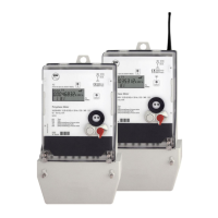
2.1 Mounting the meter
Meters form the series ITZ are suitable for wall mounting in accordance with
DIN 43 857-2.
Figure 1: Meter dimensions
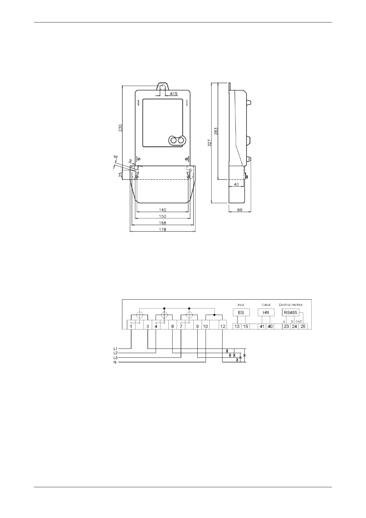
2.2 Connecting the meter
When connecting the meter it is very important to take notice of the connection diagram
which can be found in the terminal cover and also in the delivery documents:
Example:
Figure 2: Connection diagram
- 3x230/400 V; 5(60) A
- 1 control input (ES)
- 1 output Opto-MOSFET (HR)
- Electrical interface RS485
Note: Direct connected meters are to be fused against short circuits with a back-up fuse
of 63 A or 100 A and transformer operated meters in the voltage circuit with a back-up
fuse of < 10 A.