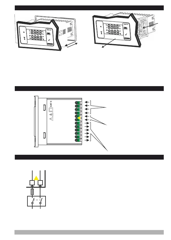
2.3 Panel Mounting and Removing
3. Electrical Wiring Diagram
3.1 Supply Voltage Input Connection of the Device
5
1-Before mounting the device in your panel, make
sure that the cut-out is of the right size.
2-Insert the device through the cut-out. If the
mounting clamps are on the unit, put out them
before inserting the unit to the panel.
3- Insert the mounting clamps to the fixing sockets
that located left and right sides of device and
make the unit completely immobile within the
panel
1-Pull mounting clamps from left and right
fixing sockets.
2-Pull the unit through the front side of the
panel
Before starting to remove the unit
from panel, power off the unit and
the related system.
c
Make sure that the power supply voltage is the same indicated on
the instrument.
Switch on the power supply only after that all the electrical
connections have been completed.
Supply voltage range must be determined in order. While installing
the unit, supply voltage range must be controlled and appropriate
supply voltage must be applied to the unit.
c
There is no power supply switch on the device. So a power supply
switch must be added to the supply voltage input.
Power switch must be two poled for seperating phase and neutral,
On/Off condition of power supply switch is very important in
electrical connection.
External fuse that on Vpower supply inputs must be on phase
connection.
External fuse that on Z power supply inputs must be on (+)
connection.
c
Power Supply Input
c
a
External
Fuse
(1A T)
Note-1
Supply
Switch
7
8
L
N
Supply Voltage
230V ( %15) 50/60Hz ,
115V ( %15) 50/60Hz ,
24V ( %15)50/60Hz ,
24V ( %15) 50/60Hz ,
Z
V ±
V ±
V ±
W ±
10...30 V 1.5 W
Must be determined in order.
Relay Outputs
2
1
3 54 6 87 9 10
P/N : ESM-3722
L
N
a
Power Supply Voltage
230V ( %15) 50/60Hz ,
115V ( %15) 50/60Hz,
24V ( %15) 50/60Hz ,
24V ( %15) 50/60Hz ,
Z
V ±
V ±
V ±
W
±
10...30 V 1.5 W
11 12
Temperature Sensor Input
NTC, PTC, PT-100 or
ProNem Mini PMI-P
Humidity Sensor Input
0/2..10V, 0/4..20mA or
ProNem Mini PMI-P
Must be determined in order.
3
2
1
1
2
Must be determined in order.
Must be determined in order.
Note-1: External Fuse is recommended