6
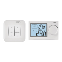
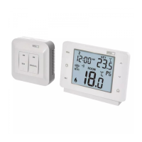
Transmitter Installation
The transmitter can be mounted onto the enclosed stand, or onto a wall.
1. Remove the rear cover.
2. Mark positions for holes.
3. Drill two holes, carefully insert the plastic wall plugs into them and
use two screws to fasten the rear thermostat cover.
4. Complete the installation by tting the switching unit onto the
attached rear part of the cover.
Receiver Installation
1. Remove the rear cover.
2. Mark positions for holes onto the wall.
3. Drill two holes, carefully insert the plastic wall plugs into them and
use two screws to fasten the rear receiver cover.
4. Connect the wires to the labelled terminals according to the wiring
diagram.
5. Complete the installation by tting the switching unit onto the
attached rear part of the cover.
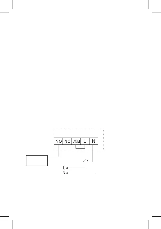
Wiring Diagram
NO normally open contact
NC normally closed contact
COM switch contact
L 230 V AC power connection
N neutral conductor
Pump/Motorised Valve Wiring Diagram
Pump/
valve
 Loading...