8 9
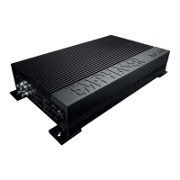
2. CONNECTIONS + TOP CONTROLS EA485
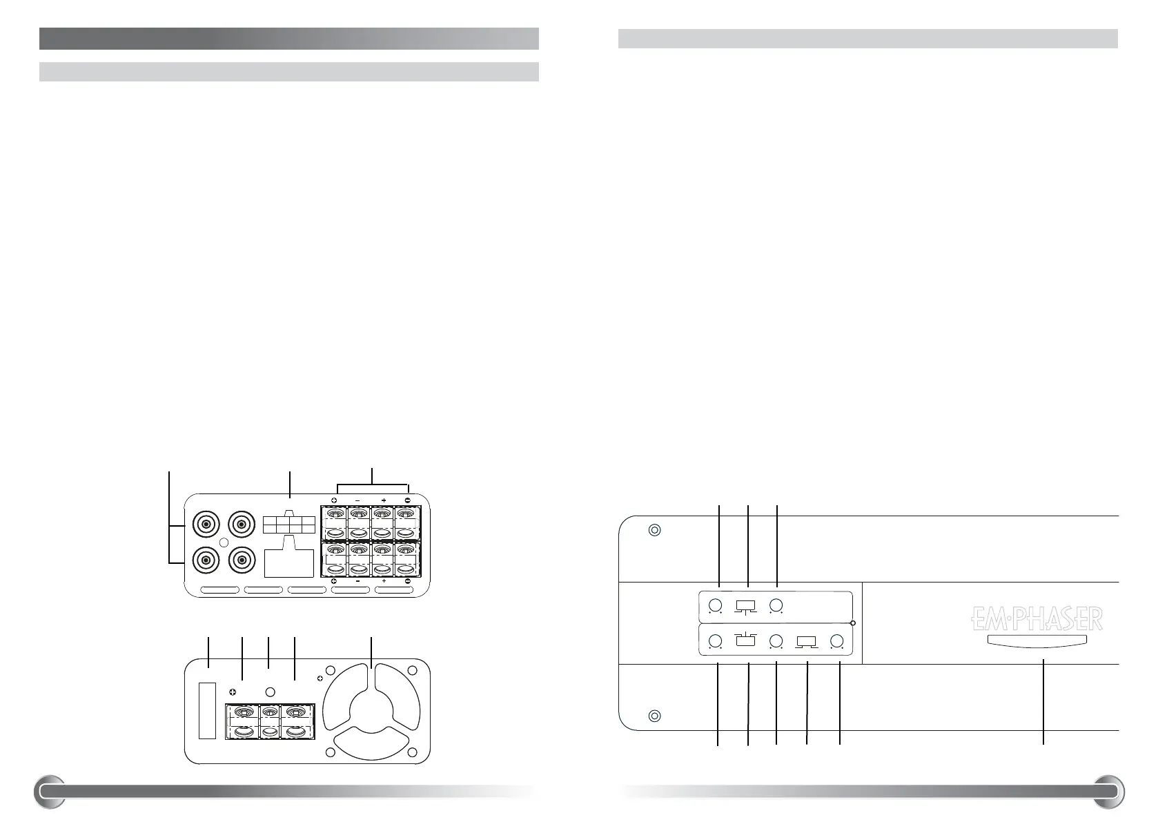
2.1 INPUTS + OUTPUTS
1 RCA INPUTS 1/2-CH + 3/4-CH
Low-level stereo RCA signal input 1/2-CH and 3/4-CH, for connection to head-unit.
2 HIGH INPUT
Molex connector terminal to insert the High level adapter (8-Pin) that picks up the
amplified speaker signals from the head unit’s front and rear outputs (if head unit
does not feature dedicated RCA line outs).
3 SPEAKER OUTPUT TERMINAL
Output terminal to connect the speakers to the amplifier in either stereo or bridged
mode. For bridge connection, use the terminals with fat polarity signs.
4 ATC FUSE HOLDER
Fuse holder for 1 x 40 A ATC fuse. Never deploy fuses of higher amperage rating.
5 “+12 V” POWER INPUT TERMINAL
Terminal to connect the amplifier to the positive +12 V pole of the car battery.
6 “REM” INPUT TERMINAL
Terminal to connect the amplifier to the automatic (remote) turn-on / turn-off lead of
the head unit.
7 “GND” POWER INPUT TERMINAL
Terminal to connect the amplifier to the chassis ground or negative pole of the car
battery.
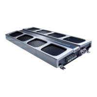
8 “FAN”
Internal fan to cool and safeguard amplifier electronics against overheating.
2.2 TOP CONTROLS
1 INPUT GAIN CONTROL 1/2-CH
Input gain potentiometer for channel 1/2-CH, to match the output voltage of the
head-unit to the amplifier’s input.
2 OPERATION MODE SWITCH 1/2-CH
Slide switch to select the operation mode of the X-over for section 1/2-CH of the
amplifier.
3 X-OVER FREQUENCY CONTROL 1/2-CH
Control potentiometer to adjust the highpass or lowpass filtering frequency point for
section 1/2-CH of the amplifier.
4 INPUT GAIN CONTROL 3/4-CH
Input gain potentiometer for channel 3/4-CH, to match the output voltage of the
head-unit to the amplifier’s input.
5 OPERATION MODE SWITCH 3/4-CH
Slide switch to select the operation mode of the X-over for section 3/4-CH of the
amplifier.
6 X-OVER FREQUENCY CONTROL 3/4-CH
Control potentiometer to adjust the highpass or lowpass filtering frequency point for
section 3/4-CH of the amplifier.
7 PHASE SWITCH 3/4-CH
Switch to select normal or inverted phase for section 3/4-CH of the amplifier.
8 SUBSONIC HIGHPASS FREQUENCY CONTROL 3/4-CH
Control potentiometer to adjust the subsonic highpass filtering frequency point for
section 3/4-CH of the amplifier.
9 POWER LED
LED bar segment to show “operating” status of the amplifier by red illumination.
Protect state of amplifier is signaled by blue state.
1
4 5
9
LPF
GAIN
HPF
X-OVER
MIN
MAX
50Hz 250Hz
GAIN
MIN
MAX
FLAT
LPF HPF
FLAT
X-OVER
50Hz 250Hz
180°
0°
PHASE SUB SONIC
15Hz 50Hz
CH1/CH2
CH3/CH4
:
:
RECEN B ES T EL ECTR ON IC FA CTORY
:
RM P -GT9 0 4
<5
5~1 0
10~1 00
>10 0
:
:
:
: 2 0 1 3 . 7 . 9
1/1
MM
+0.1
+0.2
+0.5
+1.0
-
-
-
-
:
1.
MODE
:
:
RECEN B ES T EL ECTR ON IC FA CTORY
:
RM P -GT9 0 4
<5
5~1 0
10~1 00
>10 0
:
:
:
: 2 0 1 3 . 7 . 9
1/1
MM
+0.1
+0.2
+0.5
+1.0
-
-
-
-
:
1.
2 3
:
:
RECEN B ES T EL ECTR ON IC FA CTORY
:
RM P -GT9 0 4
<5
5 ~1 0
1 0 ~1 0 0
>1 0 0
:
:
:
: 2 0 1 3 . 7 . 9
1/ 1
MM
+0 . 1
+0 . 2
+0 . 5
+1 . 0
-
-
-
-
:
1.
CH1
CH2
CH3
CH4
CH2 CH1
INPUT
CH4 CH3
HIGH INPUT
EA485
1 3
6 7 8
76 854
:
:
RECEN B ES T EL ECTR ON IC FA CTORY
:
RM P -GT9 0 4
<5
5 ~1 0
1 0 ~1 0 0
>1 0 0
:
:
:
: 2 0 1 3 . 7 . 9
1/ 1
MM
+0 . 1
+0 . 2
+0 . 5
+1 . 0
-
-
-
-
:
1.
CH1
CH2
CH3
CH4
CH2 CH1
INPUT
CH4 CH3
HIGH INPUT
EA485
FUSES
GND
REM
12V
40 A
2
:
:
RE C EN BES T EL E CT R ON I C FA C TO RY
:
RMP - G T90 4
<5
5~ 1 0
10 ~ 10 0
>1 0 0
:
:
:
:2013. 7 . 9
1/1
MM
+0 . 1
+0 . 2
+0 . 5
+1 . 0
-
-
-
-
:
1.
FUSES
CH1
CH2
CH3
CH4
CH2 CH1
INPUT
Ch1+
Ch2+
Ch3+ Ch4+
Ch3-
Ch4-
HIGH INPUT
POWER INPUT
GND
REM
12V
EA485
25AX 2
CH4 CH3
HIGH INPUT