SYS5INST ISS.3 2000
5
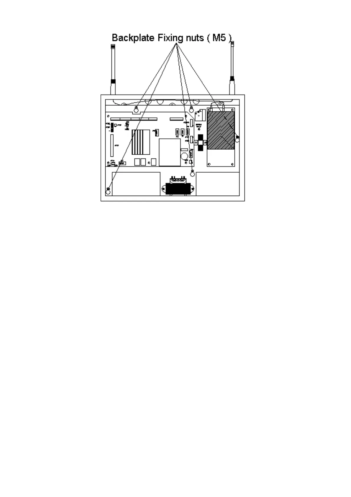
Figure. 2
5.2.3. Prior to mounting the Back Box, establish the required cable entries.
Knockouts should be made prior to fixing the Back Box to the wall, (see also Section
7).
5.2.4. Ensure that the Back Box is free of swarf and other debris before fixing to the
wall.
5.2.5. It is recommended that the Control Panel be mounted in accordance with the
site survey so that the display is at eye level. Achieve this by first securing it to the
wall via the single fixing “keyhole”, located in the top centre of the box. The box
should be hung and levelled, allowing holes to be marked out for each of the four
remaining mounting holes (one at each corner).
5.2.6. Once the Back Box is fitted to the wall, all external cabling should be run to the
box, including the provision of an unswitched 240-volt supply. The mains cable
should be dressed away from the main radio PCB and should be as short as possible.
5.2.7. Replace the Back Plate and Door assemblies by reversing the steps given above,
Ensure that all electrical connections, including the earth leads, are made.
5.2.8. Ensure that both UHF and VHF aerials are fitted to the top of the Control
Panel. To ensure correct fitment, the aerial identified with the coloured band must be
fitted to the connector identified with the coloured band. If high gain aerials are to be
used they must be positioned in accordance with the site survey.