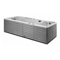
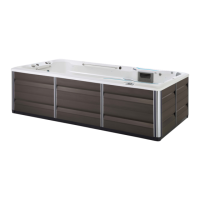
Fastlane
®
Pro Swim Unit Installation
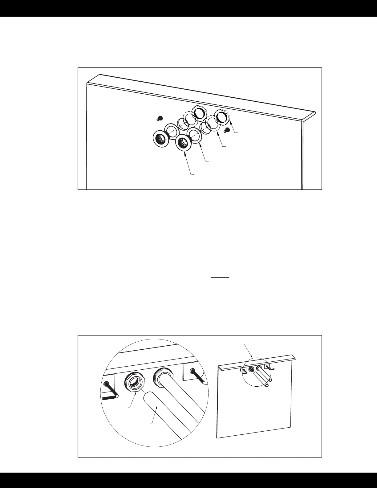
The backside of the thru-wall holes may need to be sanded at so that a proper seal can be made. Place one
of the rubber gaskets onto each thru-wall tting. The second rubber gasket will not be used in this applica-
tion. Insert the thru-wall ttings into the cut outs and place the cork gaskets onto the ttings on the backside
of the pool wall. Thread the lock nuts onto the ttings. The lock nuts should be tightened with a pair of
channel locks or strap wrench (Fig 4.27).
Thru-Wall Fitting
Rubber Gasket
Lock Nut
Cork Gasket
Fig. 4.27
The location of the Hydraulic Power Unit should be determined at this point in the installation. Unroll
lengths of 1-1/2” (38mm) exible PVC pipe from the back of the wall mount bracket to the Power Unit.
Any bends in the exible pipe MUST be gradual sweeps and not sharp to allow the hydraulic hoses to easi-
ly be fed through each conduit.
If the Hydraulic Power Unit is within 25’ (7,6m) of the pool: Each length of exible pipe should exit the
ground within 4’ (1,2m) of the Power Unit. Approximately 4’ (1,2m) of hydraulic hose is required to make
the hydraulic connections at the Power Unit.
If the Hydraulic Power Unit is more than 25’ (7,6m) away from pool: 25’ (7,6m) of exible pipe, a
junction box, and an additional length of exible pipe MUST be employed. It is at the junction box where
a step up to a larger diameter hydraulic hose occurs to reduce pressure loss and a potential reduction in per-
formance. In this case, the length of exible pipe between the wall mount bracket and junction box MUST
be 24’ 6” (7,5m). This will allow the hydraulic hoses to terminate just inside the junction box. An additional
length of exible pipe coming out of the junction box should exit the ground within 4’ (1,2m) of the Power
Unit. See Section 5: Junction Box for detailed information.
Glue the lengths of exible pipe into the thru-wall ttings on the backside of the wall mount bracket (Fig
4.28).
DETAIL A
PVC Flex Pipe
(See Detail A)
Thru-Wall
Fitting
1-1/2" (38mm)
PVC Flex Pipe
Fig. 4.28
25