Fastlane
®
Pro Swim Unit Installation
Section 12 EQUIPMENT START UP
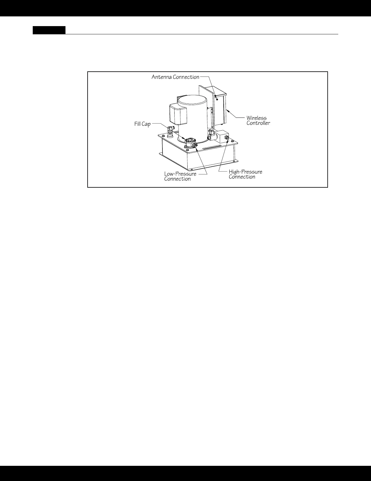
12.1 Turn the circuit breaker for the Power Unit off. Connect the hydraulic hoses from the Fastlane Pro to
the Power Unit. The low-pressure hose (connected to the Fastlane Pro) will have red tape wrapped
around the hydraulic tting. This hose will connect to the port on the ll cap. The high-pressure hose
will connect to the port on the high-pressure manifold (blue box) (See Fig 12.2).
Fig. 12.2
If the hoses attached to the Fastlane Pro are to be directly connected to the Power Unit, then use the
adapters (-8 female JIC x –6 male JIC) that were provided in the Accessories Kit.
If the 1/2" (12,7mm) run hoses are to be attached to the Power Unit, then these hoses will connect
directly to the appropriate connections on the power unit.
12.2 Unthread the ll cap and remove the oil lter by pulling up on the clear tabs at the top and lifting it out
of the opening of the ll cap assembly. Fill the Power Unit with approximately (4) gallons (14L) of
hydraulic uid (provided with the Fastlane Pro shipment). Once lled with hydraulic uid, replace the
oil lter making sure its fully seated in the ll cap assembly. Reinstall the ll cap and tighten. Install
the antenna provided by threading it onto the coaxial connection on the left side of the Power Unit
Controller’s enclosure. Turn on the unit by pressing and holding the ON/OFF button (button in the
center of the wireless transmitter). If there is no swim current created in the pool after the unit has
been running for one minute, increase the speed by pressing and holding the faster button (up
arrow) until a current is produced.
12.3 Once the Fastlane Pro is fully installed and operational, turn the system off and disconnect the hydrau-
lic return hose (hose with red tape) which connects to the ll cap. Place the hose end into the 5-gallon
(19L) bucket used to ll the power unit.
12.4 Turn on the Fastlane Pro, making sure to hold the hose rmly in your hand over the bucket. The re-
turning hydraulic uid will ow into the bucket. The system will automatically shut off when the oat
level switch inside the uid reservoir is tripped.
12.5 TURN OFF POWER TO THE UNIT AT THE CIRCUIT BREAKER.
12.6 Reconnect the hydraulic hose to the power unit and tighten. Open the ll cap and add 2 cups of
hydraulic uid. Reinstall the ll cap and tighten.
12.7 Restore power to the equipment and test the unit. The system should stay on continuously. If the sys-
tem shuts off, even intermittently, shut the power off at the circuit breaker and add an additional cup of
hydraulic uid. Restore power to the equipment and turn the unit on to test.
41