Prosonic M
Endress+Hauser
9
Installation conditions for level
measurement
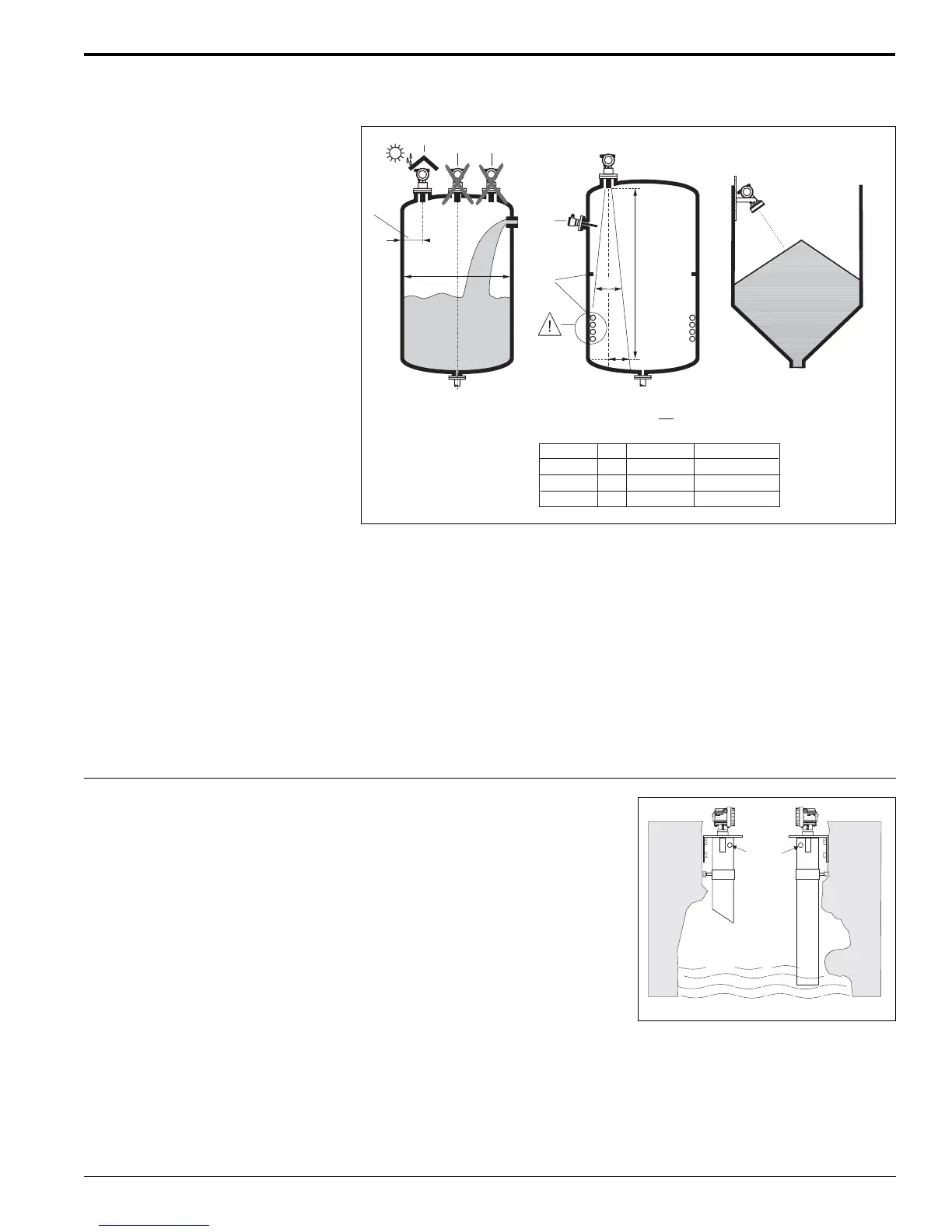
• Do not install the sensor in the middle of the tank (3). Mounting distance between
vessel wall and sensor (1) should be 1/6 of the tank diameter.
• Use a protective cover (see accessories, page 18), to protect the sensor from rain
or direct sunlight (2).
• Avoid measurements in the filling stream area (4).
• Make sure that equipment (5) such as limits swtiches, temperature sensors, etc.
are not located in the beam angle α. In particular, symmetrical equipment (6) such
as heating coils, baffles, stationary ladder rungs etc. can influence measurement.
• Align the sensor so that it is vertical to the product surface (7).
• Never install two ultrasonic measuring devices in the same vessel, as the two
signals may affect each other.
• To estimate the transmitted echo beam and its detection range, use the 3 dB
emitting angle α (see Figure above).
Installation in narrow shafts In narrow shafts with strong interference
echoes, we recommend using an
ultrasound guide pipe (e.g. PE or PVC
wastewater pipe) with a minimum
diameter of 4” (100 mm). Make sure that
the pipe does not accumulate dirt, clean
pipe at regular intervals.
1
234
5
6
1/6D
7
D
r
α
α
L
LSensor
11°
11°
6°
16 ft (5 m)
26 ft (8 m)
50 ft (15 m)
FMU 40
FMU 41
FMU 43
18.9" (480 mm)
30.3" (770 mm)
31.1" (790 mm)
r
α
2
r = L tan
ENDRESS+HAUSER
Prosonic MProsonic M
ENDRESS+HAENDRESS+HAUSERUSER
Prosonic MProsonic M
Venting
hole
 Loading...