Do you have a question about the Endress+Hauser Promass 40 and is the answer not in the manual?
Defines the intended use for measuring flow of liquids and gases.
Notes on personnel, procedures, and safety for installation and operation.
Mentions Ex documentation and general safety compliance.
Steps for returning instruments for repair or calibration.
Explains the meaning of safety icons used in the manual.
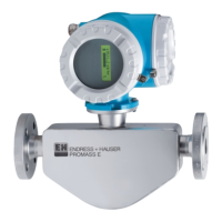
Describes the components of the Promass 40 system and naming conventions.
Details the transmitter's identification label and its information.
Details the sensor's identification label and its information.
Information on CE marking and conformity declarations.
Lists trademarks associated with the product.
Procedures for handling the device upon receipt, transport, and storage.
Information on device dimensions and required pipe fitting lengths.
Guidance on selecting an appropriate mounting position to avoid errors.
Specifics for installing in down pipes, including recommended configurations.
Importance of system pressure to prevent cavitation and boiling.
Recommendations for vertical and horizontal mounting based on fluid properties.
How orientation affects transmitter temperature based on fluid temp.
Measures for heat transfer avoidance and insulation requirements.
Requirements for pipe sections before and after the sensor.
How pipe vibrations affect the device and attachment requirements.
Information on flow limitations.
Step-by-step guide for rotating the transmitter housing.
How to rotate the local display module.
Checklist for verifying correct installation after mounting.
General steps for connecting the transmitter and signal cables.
Details terminal connections for various output/input configurations.
Options for connecting HART communicators or PCs.
Notes on potential equalisation requirements.
Ensuring IP 67 protection is maintained post-installation.
Checklist for verifying electrical connections after installation.
Describes the local display's function and layout.
How to configure and measure using the HART protocol.
Overview of the FieldTool software for service and configuration.
Guidelines for function configuration and parameter changes.
Explains error types, icons, and message meanings.
Ensures all pre-startup checks are completed.
Procedure for powering on and initial self-tests.
Details when and how to perform zero point calibration.
Step-by-step procedure for zero point adjustment.
Procedure for adjusting fluid density for accurate volume flow.
Configuration of current output using jumpers on the I/O board.
Lists accessories like HART communicators, software, etc.
General approach to troubleshooting using checklists.
Explanation of error message icons and types.
Details system error codes, causes, and remedies.
Lists additional system error codes, their causes, and remedies.
Details process error codes, causes, and remedies.
Lists additional process error codes, their causes, and remedies.
Troubleshooting steps for errors not shown by message codes.
How outputs behave during system or process errors.
Information on ordering replacement components.
Procedures for safely removing and installing electronic boards.
Steps for replacing the main fuse on the power unit board.
Records software versions and documentation changes.
Lists typical applications for the measuring device.
Describes the measuring principle and system components.
Details measured variables and input signals.
Specifies full scale values for liquids and gases.
Notes on flow rates that do not overload the amplifier.
Details of the status input (auxiliary input) functionality.
Specifications for current and pulse/frequency outputs.
Behavior of outputs during alarms.
Configuration options for the switching output.
Settings for switching points for low flow cutoff.
States that all circuits are galvanically isolated.
References pages for electrical connection details.
Lists available supply voltages.
Notes on potential equalisation requirements.
Specifies types and sizes of cable entries.
Details error limits, measured error, and zero point stability.
Specifies repeatabilities for mass and volume flow measurements.
Effect of temperature differences on measurement error.
Effect of pressure differences on measurement accuracy.
Installation requirements like inlet/outlet runs.
Environmental conditions like ambient/storage temp, protection.
Process conditions including medium temp, pressure, and limiting flow.
Formulas and coefficients for calculating pressure loss.
Details on design, dimensions, materials, and connections.
Information on the display and remote operation methods.
Lists certifications and approvals like Ex, CE, EN standards.
How to get detailed ordering information.
States no accessories for transmitter and sensor.
Lists relevant system and technical information documents.
Tables and diagrams for flange dimensions.
Detailed dimensions for ANSI CI 150 flanges.
Detailed dimensions for ANSI CI 300 flanges.
Detailed dimensions for ANSI CI 600 flanges.
Detailed dimensions for JIS B2238 10K flanges.
Detailed dimensions for JIS B2238 20K flanges.
Diagrams and dimensions for VCO connections.
Diagrams and dimensions for Tri-Clamp connections.
Diagrams and dimensions for DIN 11851 hygienic couplings.
Diagrams and dimensions for DIN 11864-1 Form A threaded unions.
Diagrams and dimensions for DIN 11864-2 Form A flanges.
Diagrams and dimensions for ISO 2853 threaded unions.
Diagrams and dimensions for SMS 1145 hygienic couplings.
| Device Type | Coriolis mass flowmeter |
|---|---|
| Measurement Principle | Coriolis |
| Process Temperature | -200 °C to +200 °C |
| Nominal diameter | DN 1 to DN 150 |
| Accuracy | ±0.1% of rate |
| Output Signals | 4-20 mA, pulse, frequency |
| Power Supply | 24 V DC |
| Housing Material | Stainless steel |
| Protection Class | IP67 |
| Approvals/Certifications | ATEX, IECEx, FM, CSA |
| Communication | HART |
| Repeatability | ±0.05 % |