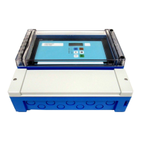
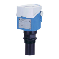
Do you have a question about the Endress+Hauser Prosonic M FMU40 and is the answer not in the manual?
Describes the intended application of the Prosonic M as a compact, non-contact level measuring device.
Outlines requirements for safe installation, commissioning, and operation by trained specialists.
Emphasizes alternative monitoring measures for safety during device configuration and maintenance.
Explains conventions and symbols used to highlight safety-relevant procedures and warnings.
Provides information about the device's nameplate, including designation, order code, and serial number.
Details the product structure and available options for FMU40, FMU41, FMU42, FMU43, and FMU44 models.
Lists the instrument and accessories included in the scope of delivery.
Covers CE mark, declaration of conformity, and registered trademarks.
Provides detailed dimensions and diagrams for FMU40, FMU41, FMU42, and FMU44 models.
Illustrates different installation methods for FMU40, FMU41, FMU42, FMU43, and FMU44 devices.
Specifies crucial installation conditions for level measurements, including shaft installations.
Details measuring ranges, nozzle mounting considerations, and sensor characteristics.
Explains the safety distance function and its role in device operation and alarms.
Provides specific hints for installing FMU40 and FMU41, including torque specifications.
Lists essential checks to perform after device installation for proper function.
Covers essential precautions and procedures for electrical connection of the device.
Details the wiring process specifically for the T12 housing connection room.
Shows the terminal assignment diagram for connecting the device.
Explains how to wire the device using the FOUNDATION Fieldbus plug connector.
Lists suitable cable specifications for FOUNDATION Fieldbus connections.
Provides recommendations for optimal connection, particularly for EMC protection.
Lists checks to perform after wiring to ensure correct connection.
Describes how to operate the device using the VU331 display and operating module.
Explains the function codes used for navigating and operating the device menus.
Details options for on-site operation, including display module and software.
Provides a step-by-step guide to operating the Prosonic M via its on-site display.
Outlines methods for remote operation using configuration tools or handheld terminals.
Describes the FieldCare asset management tool for device configuration and analysis.
Explains how to use FieldCare for menu-guided commissioning of the device.
Details how to perform signal analysis using the envelope curve feature in FieldCare.
Covers operation using FOUNDATION Fieldbus configuration programs and device description files.
Ensures all final checks are completed before starting up the measuring point.
Details methods for unlocking the device to allow parameter changes.
Explains how to reset device parameters to default values, advising caution.
Guides through the initial commissioning steps using the VU331 display module.
Outlines the standard measurement task setup process, guiding through functions sequentially.
Covers parameters related to tank shape, medium property, and process conditions.
Details the process of entering empty and full calibration distances for accurate measurement.
Explains how to set up interference echo suppression (tank mapping) for accurate readings.
Recommends using the envelope curve for measurement evaluation after basic setup.
Guides commissioning using a FOUNDATION Fieldbus configuration tool.
Details how to parametrize the Resource Block, including operating modes and status.
Explains parametrization of the Sensor Block, covering input values and configuration parameters.
Details parametrization of Analog Input Blocks for process variables and scaling.
Covers connecting function blocks for overall system configuration and device integration.
Describes how system errors are displayed on the VU331 and via FOUNDATION Fieldbus.
Lists various error codes detected by the Prosonic M and recommended actions.
Details common application errors and provides solutions for incorrect measurements.
Covers the modular repair concept and service contact information.
Provides specific guidelines for carrying out repairs on Ex-approved devices.
Explains how to find and order spare parts for the device online.
Documents changes in software versions and corresponding documentation updates.
Recommends a weather protection cover for outdoor mounting.
Details installation brackets for FMU40 and FMU41, including order numbers.
Describes screw-in flanges (FAX50) with material and sensor connection options.
Provides dimensions and order codes for cantilever accessories.
Details mounting frames with height, material, and order code information.
Provides dimensions, material, and order codes for wall brackets.
Shows dimensions for the mounting bracket compatible with FMU 42/43/44.
Describes the Commubox FXA195 HART for secure communication via USB.
Details the remote display FHX40, including technical data and housing information.
Provides a summary of key technical specifications including input and output signals.
Details data related to the FOUNDATION Fieldbus interface, including blocks and parameters.
Specifies power supply requirements, FISCO parameters, and FNICO compliance.
Outlines reaction time, reference operating conditions, and measuring accuracy.
Specifies operational limits for ambient temperature, storage, climate, and vibration.
Details operating limits for process temperature and pressure.
Presents the hierarchical structure of the device's operating menu.
Illustrates the Prosonic M's block model and the default configuration of these blocks.
Describes the Resource Block parameters used to define physical device resources.
Details the Sensor Block parameters for device calibration and configuration.
Explains the Diagnostic Block for accessing instrument error messages and status.
Covers parameters for the display module VU331, including language and format settings.
Describes the Analog Input Block's function in conditioning output signals and scaling.
Provides a list of start indices for all blocks and objects within the device.
Explains the time-of-flight measurement principle and interference echo suppression.
Defines the blocking distance and its impact on evaluating level echoes.
| Brand | Endress+Hauser |
|---|---|
| Model | Prosonic M FMU40 |
| Category | Measuring Instruments |
| Language | English |


