Do you have a question about the Endress+Hauser Prosonic T FMU 130 and is the answer not in the manual?
Step-by-step calibration guide for devices without a display.
Calibration guide for devices with a plugged-in display.
Guidelines for operating the device in explosion hazardous environments.
Explanation of symbols related to explosion protection.
Explanation of symbols used for electrical connections.
Overview of applications and available measuring ranges for Prosonic T.
Description of the 2-wire loop-powered measuring system configurations.
Description of the 4-wire separate power supply measuring system configurations.
Explanation of the blocking distance and its importance for accurate measurement.
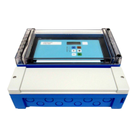
Details on the device housing, including cable entry and dimensions.
Instructions for mounting using a counter nut or welded sleeve.
Guidelines for mounting the sensor on a vessel nozzle.
Instructions for mounting using a mounting bracket.
Mounting with an adapter flange (parallel thread).
Mounting with an adapter flange (conical thread).
Instructions for mounting the FMU 232 with a mounting bracket.
Instructions for mounting the FMU 232 with a slip-on flange.
Details on the FMU 232 housing.
Guidelines for using shielded instrumentation cable for optimal signal integrity.
Diagrams illustrating electrical connection configurations for different FMU models.
Instructions for connecting the Commubox interface to a PC.
Basic operation using device push-buttons without a display or matrix.
Procedure for resetting the instrument to factory settings.
Steps for performing empty and full calibration.
How to protect settings against unauthorized changes.
How to unlock protected settings.
Operation using the device's push-buttons and plug-in display.
Operating the Prosonic T using the HART Communicator DXR 275.
Initial setup and basic configuration steps for the device.
Access to other configuration settings beyond basic calibration.
Settings to fine-tune performance and echo quality.
How to view measured values and device information via matrix fields.
Procedure to reset the instrument to factory default settings.
Important notes regarding the selection and use of length units.
Selecting the appropriate application for the measurement.
Step-by-step guide to entering a linearization curve.
How to set the analog current output after linearization.
Common error and warning messages during linearization.
Using volumetric measurement for linear level-to-volume relationships.
Method for entering linearization data by emptying the vessel.
Method for manually inputting level and volume pairs for linearization.
Calculation of linearization curves for cylindrical horizontal tanks.
Important notes regarding current output settings and behavior.
Configuration for continuous analog current output.
Configuration for switch current output.
Interpreting and using the echo quality indicator.
Guidance on sensor placement for optimal echo detection.
How to activate echo suppression for interference signals.
Notes on exceeding the maximum operating temperature.
Setting delay time to prevent false alarms from short-term lost echoes.
How to correct height readings using the actual height input.
Adjusting the first echo factor to manage double echoes.
Methods for locking the device's keyboard and programming.
Specific instructions for locking the device using the keyboard.
Guide to identifying and resolving operational faults (alarms and warnings).
| Device Type | Ultrasonic Level Transmitter |
|---|---|
| Measuring Principle | Ultrasonic |
| Housing Material | Aluminum or stainless steel |
| Protection Class | IP 66 / IP 67 |
| Application | Level measurement in liquids and solids |
| Process Temperature | -40 to +80 °C |
| Output Signal | 4 to 20 mA |
| Power Supply | 24 V DC |
| Communication | HART |
| Ambient Temperature | -40 to +60 °C |
| Display | LCD |
| Approvals | ATEX, IECEx |


