D
Dawn PerryAug 5, 2025
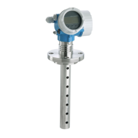
Why is my Endress+Hauser Radar measuring incorrectly?
- AAudrey BurkeAug 5, 2025
If your Endress+Hauser Radar device is measuring incorrectly, it might be due to a parameter configuration error. Review the parameter configuration and correct any mistakes.