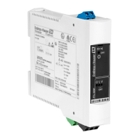
Electrical connection Nivotester FTL325P single-channel
14 Endress+Hauser
Connectable sensors:
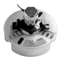
• Liquiphant FTL51B, FTL62 and FTL64 with FEL67
• Liquiphant M FTL50(H), FTL51(H), FTL51C with FEL57
• Liquiphant S FTL70/71 with FEL57
• Soliphant M FTM50, FTM51, FTM52 with FEM57
Blue terminal blocks at top for hazardous area
• Twin-core connecting cable between the Nivotester and sensor, e. g. commercially available
instrument cable or cores in a multi-core cable for measurement purposes
• Use a shielded cable in the event of increased electromagnetic interference, e. g. from
machines or radio equipment.
Only connect the shield to the grounding terminal in the sensor. Do not connect it to the
Nivotester.
5.2.3 Connecting the signal and control systems
Gray terminal blocks at bottom for the non-hazardous area
Relay function depending on the level and safety mode
If a device with high inductance is connected (e. g. contactor, solenoid valve), a spark arrestor
must be installed to protect the relay contact .
5.2.4 Connecting the supply voltage
Green terminal block at bottom
A fuse is integrated into the power supply circuit. An additional fine-wire fuse is not
necessary. The Nivotester is equipped with reverse polarity protection.
5.3 Special connection instructions
5.3.1 Connecting the outputs
A0039183
8 Connecting the outputs
A Level, limit signal
B Fault, alarm
5.4 Ensuring the degree of protection
• IP20 (as per IEC/EN 60529)
• IK06 (as per IEC/EN 62262)
 Loading...