Technical Data
General Information
Manufacturer Endress+Hauser GmbH+Co.
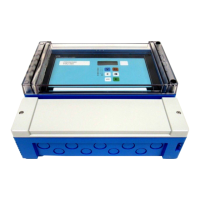
Instrument Ultrasonic transmitter
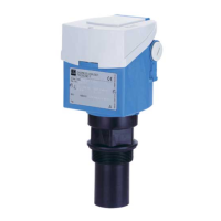
Designation Prosonic FMU 860, 861, 862
Technical documentation
Version
Technical data
TI 190F/00/en
07.99
according to DIN 19259
Application
Non-contact,, continuous level measurement in liquids and solids,
for determining flowrates in open channels and weirs, water levels or for controlling screens and pumps
Operation and System Design
Measuring principle Ultrasonic echo, time of flight measurement
Modularity – FMU 860: One signal input for level measurement
– FMU 861: One signal input for flow measurement
– FMU 862: Two signal inputs for differential level
measurement
Mechanical Construction
Transmitters – IP 66 field housing for post and wall mounting
– Separate operating unit (keyboard and display) for
control panel mounting or for rack mounting 3 m
connecting cable supplied
– IP 40 plastic housing with electronics for connecting a
separate operating unit
– IP 10 mounting plate for connecting a separate
operating unit
Ultrasonic sensors FDU 80, 80F, 81, 81F, 82, 83, 84, 85, 86
Separate switch input external passive limit switch (NO contact or NC contact) or
PNP switch, 24 V, maximum short-circuit current 20 mA
Separate temperature sensor to compensate for temperature effects on time of flight in
open channels, NTC version
Signal transmission 4…20 mA analogue signal, can be switched to 0…20 mA
Input
Measured variable Time of flight measurement of the ultrasonic pulse using
ultrasonic sensors
Measuring range 2...70 m depending on the ultrasonic sensors
Output Analogue output
Output signal – 4…20 mA, switchable to 0…20 mA (can be inverted),
superposed digital communications signal INTENSOR
or HART
– FMU 862: same values for second signal input,
simultaneous switchover of Channel 1 to 0…20 mA
– with plug-in module and also serial interface
– 4-mA level for coupling
Output on error – 0…20 mA:
–10 % (-2 mA), +110 % (22 mA), HOLD (last current
value is held)
– 4…20 mA:
–10 % (2.4 mA), +110 % (21.6 mA), HOLD (last
current value is held)
Current limit 24 mA
Integration time 0…300 s
Load max. 600 Ω
Effect of load negligible
12

 Loading...


