Console Operation
STANDARD TO METRIC CONVERSION
The console allows the user to display the readout in either standard or metric units
depending on the user’s needs. To adjust the readout, press the PAUSE/RESET button
for 2 seconds. The current readout, whether standard or metric, is displayed on the
MESSAGE WINDOW. Use the MORE /LESS buttons to change the unit of measure. To
conrm the selection, press the ENTER/SCAN button.
CONSOLE TESTING
Display Test
The display test allows the user the ability to test the MESSAGE WINDOW and the PRO
FILE WINDOW display for correct functionality. The display test is used perform a visual
hardware check by allowing the MESSAGE WINDOW and the PROFILE WINDOW display the
opportunity to display every LED in predetermined sequences. The MESSAGE WINDOW
will display and cycle through the characters <0, 1, ... , 9> and <A, B, ... , F>. The PRO
FILE WINDOW will display and cycle through all the columns and rows illuminating an
entire column or row with every cycle. To access the display test, rst remove power
and then reapply power to the elliptical. Once the elliptical is powered on, press the
MORE and LESS buttons together and hold for 2 seconds.
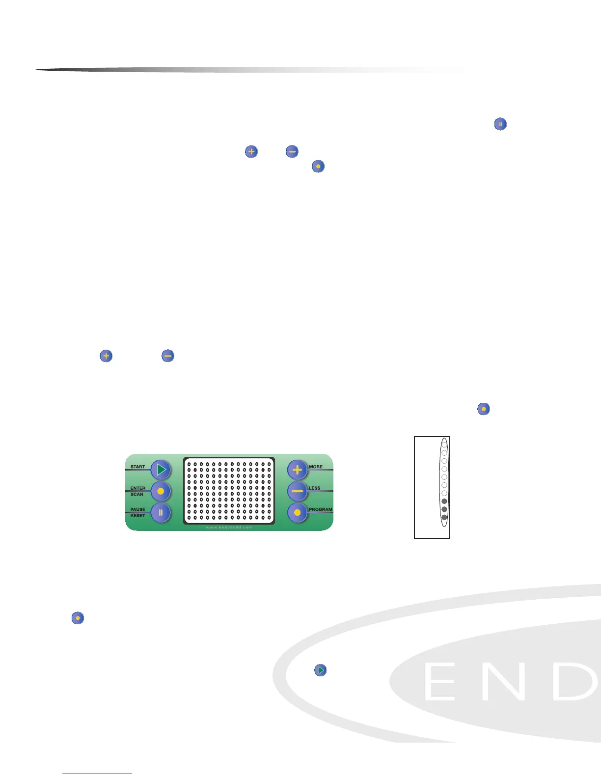
Button Test
The button test allows the user to determine if the console’s buttons are fully func-
tional. Once the display test has been performed, press the ENTER/SCAN button to
activate the button test. LEDs will be displayed next to the buttons as shown in the
gure below.
Pressing each button individually will turn o the adjacent LED signifying that each
of the pressed buttons are active. When all the console buttons have been pressed,
all the LEDs should be o in the PROFILE WINDOW display indicating that the buttons
are working correctly. To exit this test once it has been completed, press the PROGRAM
button.
Resistance Motor Test
Perform the resistance motor test to verify functionality of the resistance motor. En-
ter Quick Start Mode by pressing the START button to show the resistance level in
the PROFILE WINDOW. The left column LEDs will illuminate as resistance is increased. See
the Resistance Level Chart for reference.
13
Console Instructions
QUICK START MODE - The Quick Start Program allows the user to quickly start using the
machine without using the preset programs. To enter Quick Start (Manual) mode: Plug power
adapter into wall outlet. Plug the adapter cord into the power input located on the lower front-
left side of the unit. The Message Window will display “PRESS PROGRAM KEY TO BEGIN”.
Press START/SCAN button instead. Start exercising. The Resistance Level can be changed at
any time by pressing the +/- buttons. Time is set at 30 minutes. Weight is set at 150 lbs.
LAP DISPLAY - Shows your progress around an virtual track. This also shows the tension
level in the first column. Every dot in the tension column represents an increment of two.
Tension is adjustable from 1-20. One dot on the lap counter is equal to 15 revolutions. One
revolution is equal to 2 steps. Current position on track will blink.
Lap Progress Display
19-20
17-18
15-16
13-14
11-12
9-10
7-8
5-6
3-4
1-2
Lap Progress
Starts Here
Tension
Level
LAP DISPLAY/COUNTER - In Heart Rate Mode the lap progress display also shows % of
Maximum Heart Rate and Tension level.
Lap Counter
91-95
86-90
81-85
76-80
71-75
66-70
61-65
56-60
51-55
<50
% of Maximum
Heart Rate
Shows current lap.
Value starts at 0.
Resistance Level Chart
Resistance
Level
36
Button Test Display