AC VOLTAGE SELECTION 3 x 208/240/480 V (not for 600V input models)
The input voltage setting of the charger is made using two devices:
1) BOARD FOR INPUT VOLTAGE SELECTION (BVS)
(two selectable ranges: 200-250V or 440-524V)
2) PLUGS FOR INPUT VOLTAGE ADJUSTMENT
(ve taps within the selected range, see next chapter)
The BOARD FOR INPUT VOLTAGE SELECTION has three metal
bars, to be connected in one of the two congurations represented
on the picture inside the charger.
PROCEDURE:
• Check that the charger is disconnected from AC input and battery
• Open the cabinet and remove the plastic protection over the BVS
• Remove the metal bars and position them in the correct conguration
• Fix the nuts carefully
• Mount the plastic protection over the BVS
• Close the cabinet
Metal bars in position 200-250 Vac Metal bars in position 440-524 Vac
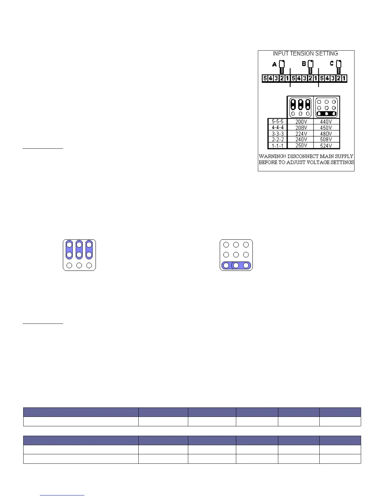
AC INPUT VOLTAGE ADJUSTMENT
The local AC input voltage must be measured with an adequate voltmeter, then the charger input must be
adjusted by moving the three wires marked with the letters A, B, C on the
PLUGS FOR INPUT VOLTAGE ADJUSTMENT.
PROCEDURE:
• Check that the charger is disconnected from AC input and battery
• Open the cabinet
• Disconnect the wires A, B, C from the original position
• Connect the wire A, B, C to the desired position
• Close the cabinet
MODELS WITH INPUT VOLTAGE 3x600V
POSITION 5 4 3 2 1
VOLTAGE 550V 575V 600V 610V 620V
MODELS WITH INPUT VOLTAGE 3x208/240/480V
POSITION 5 4 3 2 1
BVS AT 240 Vac 200V 208V 224V 240V 250V
BVS AT 480 Vac 440V 450V 480V 508V 524V
9