Do you have a question about the Energomera CE102 and is the answer not in the manual?
Details the meter's electronic register, tariff programming, and data archiving capabilities.
Describes the measurement of voltage, current, frequency, and active power.
Explains the electric test output and its proportionality to consumed power.
Covers the logging of events, states, and parameter programming.
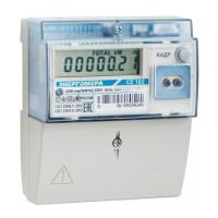
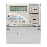
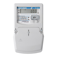
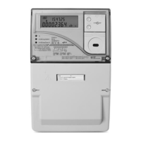
Information about the liquid-crystal display (LCD) and control button.
Details optical port and EIA-485 interface capabilities for data exchange.
Explains the designation structure used to specify meter modifications.
Specifies the conditions for indoor mounting and environmental operation.
Details resistance to climatic influences, dust, water, and vibration.
Presents the meter's technical specifications according to IEC standards.
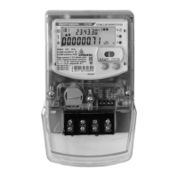
Describes the power metering principle and the meter's physical construction.
Procedure for visual examination after unpacking to check for damage and seals.
Information on factory default settings and the need for potential changes.
Step-by-step guide for connecting the meter to the AC network and systems.
Explains how the meter measures, saves, and displays energy consumption data.
Displays energy consumption on a cumulative total, per tariff, and date/time.
Shows measured network parameters like voltage, current, power, and frequency.
Provides access to service information such as firmware checksum and time correction.
Describes the meter's automatic cycling through Group 1 data.
Enables reading consumption data when the network voltage is absent.
Covers display of tariff, error, and other operational status messages.
Details obtaining information via PC using optical or EIA-485 interfaces.
Focuses on systematic monitoring of operation, time accuracy, and connections.
Outlines the procedure and frequency for periodic meter verification.
Procedure for sending meters for repair or adjustment based on verification results.
Guidance on performing the lithium battery replacement procedure.
Specifies manufacturer packaging requirements and ambient storage conditions.
Details requirements for transporting meters in closed vehicles and extreme conditions.
| Rated Voltage | 230 V |
|---|---|
| Frequency | 50 Hz |
| Maximum Current | 60 A |
| Current | 5-60 A |
| Accuracy Class | 1.0 |
| Operating Temperature Range | -40°C to +70°C |
| Mounting | DIN rail |
| Type | Single-phase |
| Display | LCD |
| Communication interface | RS-485 |