Do you have a question about the Energomera CE308 and is the answer not in the manual?
Describes the meter's primary function: measuring active and reactive electrical energy in three-phase AC circuits.
Explains the structure of meter designation, including integrated communication modules and additional functions.
Provides information regarding the meter's certification details.
Outlines environmental parameters like temperature, humidity, and pressure for normal operation.
Details environmental conditions for meters installed indoors or in protective cabinets.
Covers resistance to climatic influences, dust, water, mechanical impacts, and vibrations.
Lists guaranteed technical specifications and limits of permissible errors.
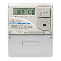
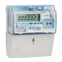
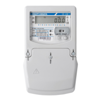
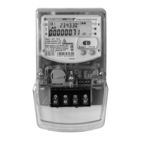
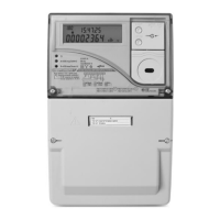
Describes the meter's construction, materials, and front panel components.
Instructions for visually inspecting the meter for damages and checking seals after unpacking.
Information about factory settings and authorized companies for configuration changes.
Guidance on connecting the electric meter to a three-phase AC network with a rated voltage.
Illustrates connection diagrams for meter terminals and various interface types.
Details on connecting TM1 and TM2 pulse outputs for energy metering and relay functions.
Explains alarm relay (AR) connections for implementing alarm functions.
Diagram for connecting a backup power source to specific meter versions.
Overview of data exchange interfaces including RS485, PLC, GSM, Ethernet, and others.
Procedure for replacing the integrated or additional lithium cell for the real-time clock.
Information on how to configure the meter, referencing the manufacturer's manual.
Details on how meter readings are displayed on the LCD, including display window options and transformation ratios.
Information on viewing active/reactive imported/exported energy by tariffs and phases using OBIS codes.
Details the limits of permissible basic relative error for measuring current values.
Details the limits of permissible basic relative error for measuring phase voltage.
Provides dimensional drawings and visual representation of the CE308 S31 meter.
Provides dimensional drawings and visual representation of the CE308 S34 meter.
Illustrates the connection diagram for a CE308 230V 5(10)A meter via three current transformers.
Illustrates the connection diagram for a CE308 57.7V 5(10)A meter via current and voltage transformers.
Illustrates the direct connection diagram for CE308 230V 5(60)A and 5(100)A meters.
| Frequency | 50 Hz |
|---|---|
| Mounting | DIN rail |
| Display | LCD |
| Type | Electricity Meter |
| Accuracy Class | 1.0 |
| Operating Temperature | -40°C to +70°C |
| Communication Interface | RS-485 |