30 31
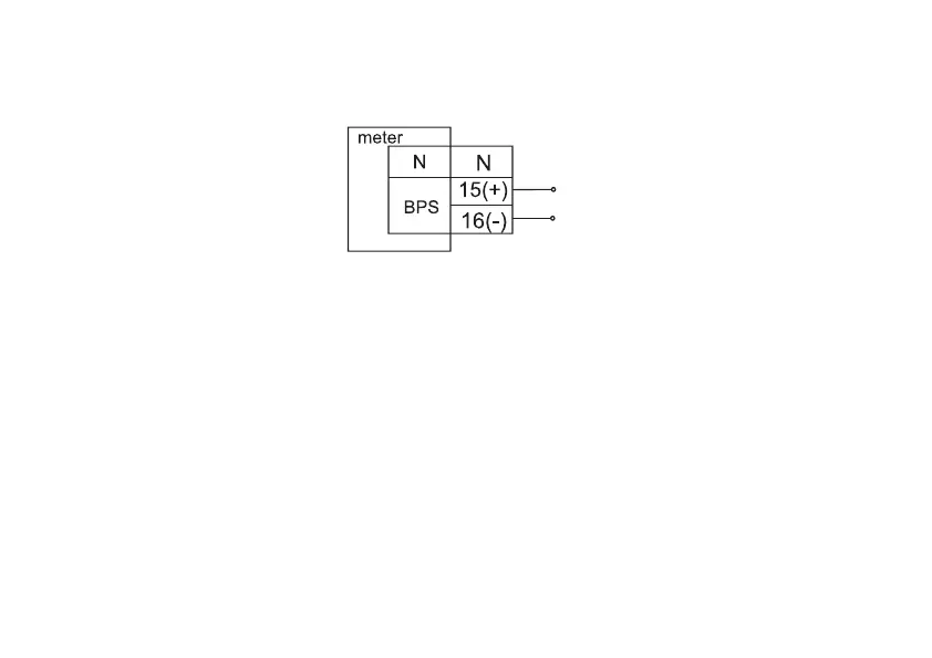
3.4.3 Backup power source (BPS) connection diagram
Backup power source connection diagram (only for meter versions CE308 S31, СЕ308 S34 with J).
U
power
=9-24 V, I
power
=800-300 mA (depending on the U
power
)
Figure 3.5 – BPS connection diagram
3.4.4 Connection of meter interfaces
The meter provides data exchange with external data processing devices via the optical port and RS485 interface
in accordance with the protocols of GOST IEC 61107-2011 and DLMS/COSEM (for meter versions Z).
The optical port is designed in accordance with GOST IEC 61107-2011. The optical port is intended for local
connection of the meter via an optical head connected to the PC serial port.
3.4.4.1 RS485 interface connection
The meter versions with an RS485 interface make it possible to combine up to 256 devices (meters) on one
common bus. When connecting two or more metering devices, it is necessary to assign an individual address for each
one. The meter’s RS485 interface connection diagrams are shown in Figure 3.6 a, b.
If the ground potentials at the installation sites of meters and data concentrator unit (DCU) are equal, then it is