32
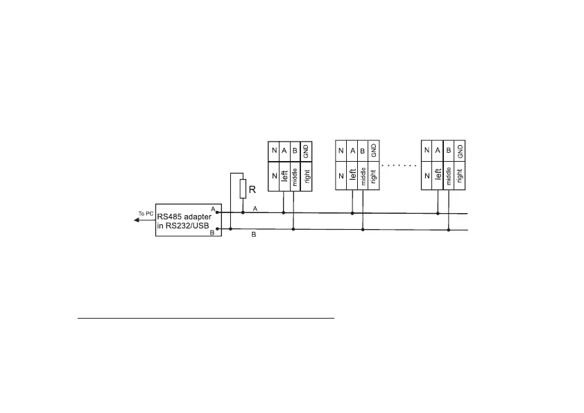
enough to connect pin 17 (right) and 13 (for CE308 S31, S34) to the zero potential point, otherwise take potential
equalization measures.
In the event that the length of the communication lines does not exceed several meters and there are no sources
of interference, then the connection diagram can be significantly simplified by connecting the meter to the DCU
or PC using only two signal wires A and B. The exact resistance value of the terminal resistors
5
, as well as the need
to use them, should be determined during the preliminary survey of the facility. In general, if the communication line
is up to 1000 m and the exchange rate is up to 9600 bod, the use of terminal resistors is not recommended
6
.
а) connecting CE308 S31, S34 using connector 17 (see Figure 3.1a)
Biasing resistors (+R) and (-R) (nominal 100 kΩ) are installed in the meter and are always connected to the A
and B lines, respectively. Unused biasing resistors with resistance of 560 Ω are also installed. To activate the resistors,
it is necessary to close the contact pads located in the area of connector 19 (see Figure 3.1a): «R-» with «B», «R+»
5
It also depends on the cable brand, its length, linear resistance, as well as the input impedance of all other receivers in the line
6
If the terminal resistor is already installed inside the data concentrator unit, it can be disconnected using the appropriate
microswitches (jumpers) of the data concentrator unit.